Sludge dewatering extrusion die

A technology of sludge dehydration and extrusion die, which is applied in the direction of water/sludge/sewage treatment, sludge treatment, chemical instruments and methods, etc. It can solve the problems of affecting the extrusion effect, low drainage efficiency, and reduced sludge moisture content, etc. problems, to achieve the effect of improving drainage efficiency, improving operating efficiency, and shortening operating time

Inactive Publication Date: 2019-09-10
GUANGDONG HANDSOME INTELLIGENT EQUIP CO LTD
View PDF14 Cites 0 Cited by
  • Summary
  • Abstract
  • Description
  • Claims
  • Application Information

AI Technical Summary

Problems solved by technology

[0002] Domestic sludge needs to be dewatered to reduce its weight and volume for recycling or treatment. The dehydration of domestic sludge is usually carried out by squeezing the sludge with corresponding equipment. These sludge dewatering equipment usually include sludge Dewatering devices and supporting auxiliary facilities. The existing sludge dewatering devices are usually horizontal and occupy a large area, and the sludge is easy to flow downward under the action of its own gravity and affect the extrusion effect. It is often difficult to make the sludge The moisture content of the mud is reduced to a predetermined requirement
At present, some vertical sludge dewatering devices have also appeared on the market, which usually squeeze the sludge through an extrusion die that can move up and down. Usually, only a filter screen is set on the extrusion part of the extrusion die for extrusion. The discharged water passes through and flows out naturally, the drainage efficiency is low, and the direction of the water flow is relatively chaotic, which is prone to local water accumulation and cannot be discharged in time and is reabsorbed by the sludge, which will affect the dehydration effect and operating efficiency

Method used


Image

  • Sludge dewatering extrusion die
  • Sludge dewatering extrusion die
  • Sludge dewatering extrusion die

Examples


Embodiment Construction

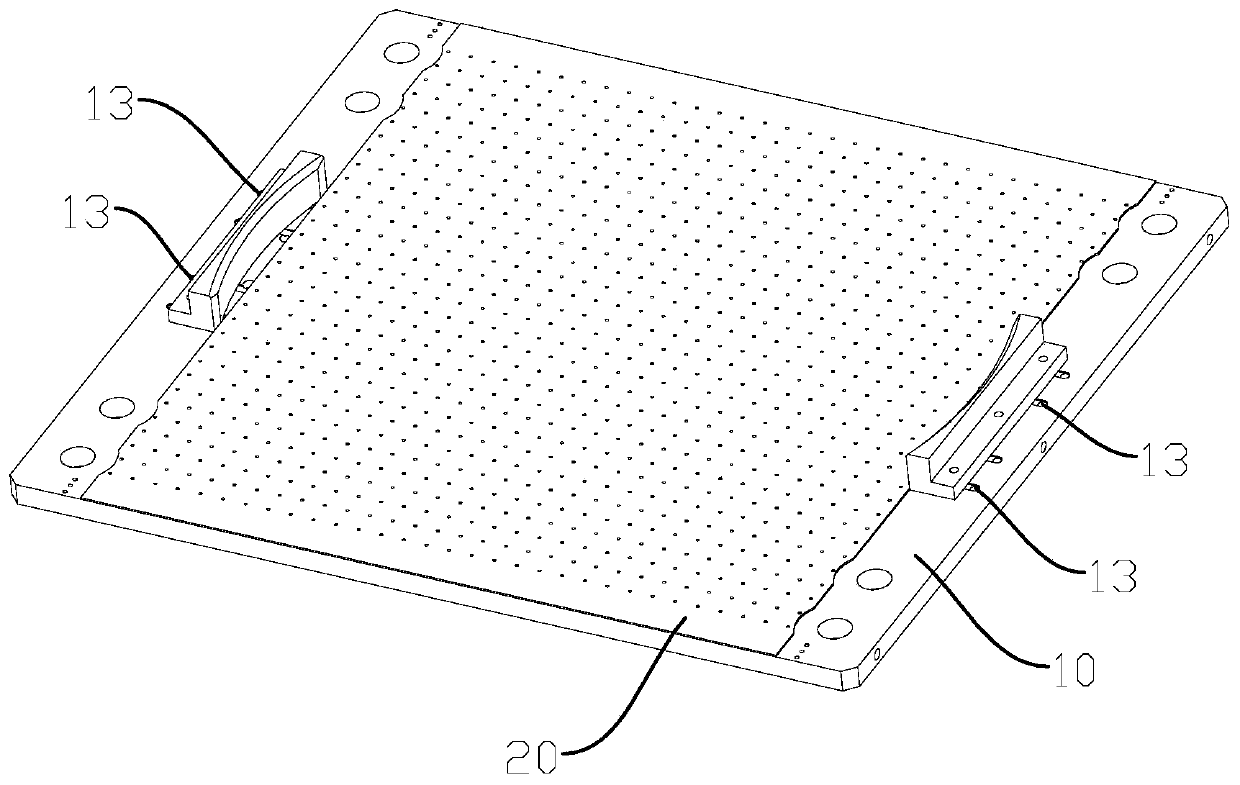
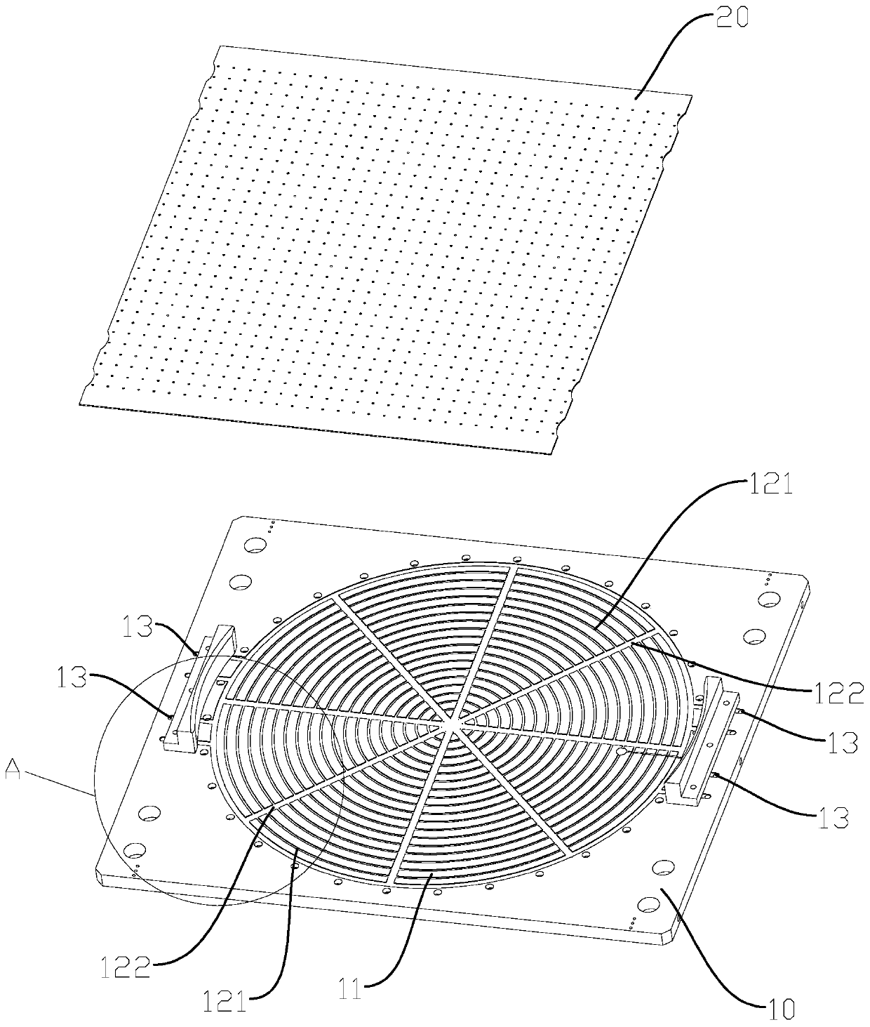
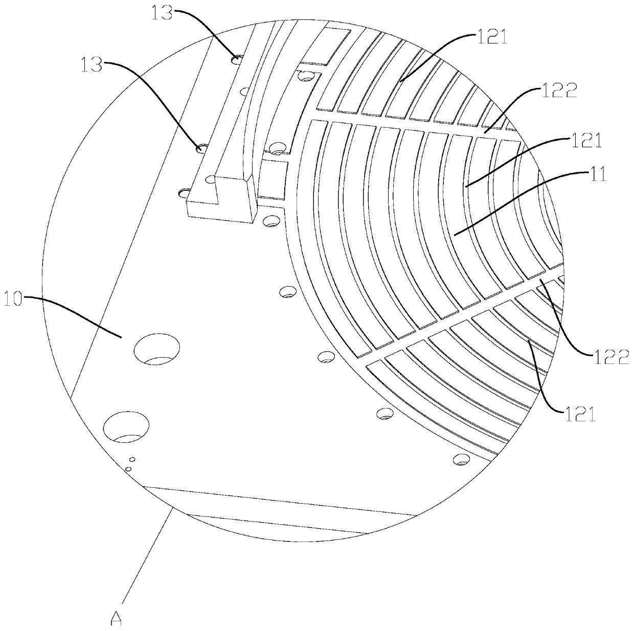
[0017] refer to Figure 1 to Figure 3 , a preferred embodiment of the present invention, a sludge dewatering extrusion die, comprising an extrusion die main body 10, an extrusion die main body 10 has an extrusion part 11, and the extrusion part 11 is provided with a diversion groove, and the diversion groove Spreading outward from the center of the extrusion part 11, the extrusion die main body 10 is provided with a drain 13 communicating with the diversion groove. In the present invention, since the outwardly diffused diversion grooves are provided on the extruding part 11, the water generated during the sludge extrusion process can gather in the diversion grooves and be guided by the diversion grooves to flow outward and pass through Drainage through the outlet 13 is less prone to turbulent flow and silting, can effectively improve drainage efficiency, reduce the amount of water reabsorbed by sludge, can effectively improve the dehydration rate of sludge, and also helps to s...


PUM


Abstract

A sludge dewatering extrusion die comprises a main body of an extrusion die, wherein the main body of the extrusion die has an extrusion portion, a flow guide groove is arranged on the extrusion portion, the flow guide groove diffuses outwards from the center of the extrusion portion, and a drain port communicated with the flow guide groove is arranged on the main body of the extrusion die. In thepresent invention, as the flow guide groove which diffuses outwards is arranged on that extrusion portion, the water generated during the sludge extrusion process can be collected in the flow guide groove and guided outwards by the flow guide groove and discharged through the drain port, turbulence and deposition are not easy, the drainage efficiency can be effectively improved, the amount of water re-absorbed by sludge can be reduced, the dewatering rate of the sludge can be effectively improved, but also the operation time of extrusion dewatering can be shortened and the operation efficiency can be improved.

Description

technical field [0001] The invention relates to the field of sludge dewatering equipment, in particular to a sludge dewatering extrusion die. Background technique [0002] Domestic sludge needs to be dewatered to reduce its weight and volume for recycling or treatment. The dehydration of domestic sludge is usually carried out by squeezing the sludge with corresponding equipment. These sludge dewatering equipment usually include sludge Dewatering devices and supporting auxiliary facilities. The existing sludge dewatering devices are usually horizontal and occupy a large area, and the sludge is easy to flow downward under the action of its own gravity and affect the extrusion effect. It is often difficult to make the sludge The reduction of the moisture content of the mud is subject to predetermined requirements. At present, some vertical sludge dewatering devices have also appeared on the market, which usually squeeze the sludge through an extrusion die that can move up and ...

Claims


Application Information

Patent Timeline
Patent Type & Authority Applications(China)
IPC IPC(8): C02F11/121
CPCC02F11/121
Inventor 罗躜黄安全聂建秋
Owner GUANGDONG HANDSOME INTELLIGENT EQUIP CO LTD
Why Eureka
Try Eureka