
Longitudinal and transverse coupled pressure application-based fatigue test device

A fatigue test, cross-arm technology, applied in the direction of measuring devices, using applied stable tension/compression to test the strength of materials, instruments, etc.

Inactive Publication Date: 2019-09-10
SICHUAN UNIV
View PDF8 Cites 2 Cited by
  • Summary
  • Abstract
  • Description
  • Claims
  • Application Information

AI Technical Summary

Problems solved by technology

[0002] like Figure 7 As shown, in the pressure vessel crack fatigue test, it is necessary to carry out longitudinal and transverse two-way coupling force. In the actual working environment, some parts are not only subjected to longitudinal force, but also transverse force. It is difficult for traditional fatigue testing machines to Stretch or compress while simultaneously applying pressure in the lateral direction

Method used


Image

  • Longitudinal and transverse coupled pressure application-based fatigue test device
  • Longitudinal and transverse coupled pressure application-based fatigue test device
  • Longitudinal and transverse coupled pressure application-based fatigue test device

Examples


Embodiment Construction

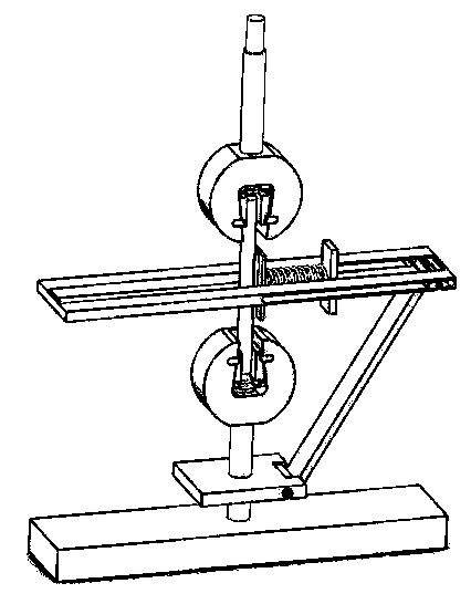
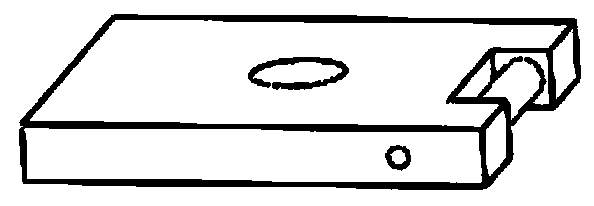
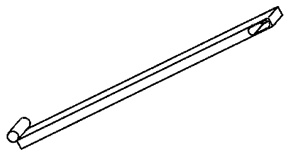
[0019] like figure 1 Shown is a two-way force fatigue test device, including a base, an oblique arm, a slide bar, a cross arm, and a fixture. The base and the lower end of the oblique arm are connected by an iron column and fixed with two screws, and the oblique arm can freely rotate left and right around the iron column. The upper end of the oblique arm is also interspersed with an iron column. The oblique arm can freely rotate left and right around the column. The iron column is placed in the horizontal chute at the right end of the cross arm. Clamp the test piece firmly. Under the force of the oblique arm, the iron column can slide left and right along the chute, compressing or stretching the spring on the left side of the slide bar, thereby exerting lateral pressure or tension on the specimen. This structure can be applied to a general standard fatigue testing machine, so as to apply tension or compression in the longitudinal direction and simultaneously apply compressi...


PUM


Abstract

The invention discloses a longitudinal and transverse coupled pressure application-based fatigue test device. In pressure vessel crack fatigue tests, longitudinal and transverse bidirectional coupledpressure application needs to be carried out, in practical working environments, certain parts are not only stressed in the longitudinal direction, but also stressed in the transverse direction, and the traditional fatigue testers are difficult to apply pressure in the transverse direction when carrying out stretching or compression in the longitudinal direction. The invention mainly aims at realizing longitudinal pressure application and transverse pressure application on test pieces at the same time through a longitudinal unidirectional pressure application manner. A hydraulic servo pump station longitudinally applies pressure on a clamp to ensure that a base generates a relative movement trend in the longitudinal direction, and an oblique arm is driven to ensure that a sliding rod generates a movement trend on a cross arm, so that transverse pressure is applied on a test piece and then unidirectional pressure application is successfully converted into bidirectional pressure application. The fatigue test device is capable of simplifying the test equipment, saving the cost and connecting the transverse and longitudinal pressure application, thereby making the test process more reasonable and making the test result more referential.

Description

technical field [0001] The invention is suitable for general digital standard fatigue testing machine, especially for the test of tension and compression of test piece. Background technique [0002] like Figure 7 As shown, in the pressure vessel crack fatigue test, it is necessary to carry out longitudinal and transverse two-way coupling force. In the actual working environment, some parts are not only subjected to longitudinal force, but also transverse force. It is difficult for traditional fatigue testing machines to Stretch or compress while applying pressure in the lateral direction. Therefore, inventing a longitudinal and transverse fatigue test device is of great significance for ensuring the reliability of fatigue test results. like Figure 8 Shown is the force analysis of the mechanism in operation, where . Contents of the invention [0003] The main problem to be solved by the present invention is the situation of simultaneously applying force to the test p...

Claims


Application Information

Patent Timeline
Patent Type & Authority Applications(China)
IPC IPC(8): G01N3/14
CPCG01N3/14G01N2203/0017G01N2203/0019G01N2203/0035G01N2203/0073
Inventor 龙伟胥鑫毛志辉
Owner SICHUAN UNIV
Learn More