Visual tracking system and method

A technology for visual tracking and targets to be tracked. It is applied in the parts of TV systems, TVs, color TVs, etc., and can solve the problems of inability to obtain clear images of small targets, limited field of view and resolution, and inability to high frame rates. Achieve the effect of increasing the upper limit of the available frame rate, improving the tracking success rate and accuracy, and fast response speed

Active Publication Date: 2019-09-10
HUAZHONG UNIV OF SCI & TECH
View PDF6 Cites 8 Cited by
  • Summary
  • Abstract
  • Description
  • Claims
  • Application Information

AI Technical Summary

Problems solved by technology

However, there are two problems: one is that the images acquired by the gimbal will be blurred when it is in motion, so it cannot be tracked at a high frame rate; Clear images over a large field of view

Method used


Image

  • Visual tracking system and method
  • Visual tracking system and method
  • Visual tracking system and method

Examples


Embodiment Construction

[0046] In order to make the object, technical solution and advantages of the present invention clearer, the present invention will be further described in detail below in conjunction with the accompanying drawings and embodiments. It should be understood that the specific embodiments described here are only used to explain the present invention, not to limit the present invention. In addition, the technical features involved in the various embodiments of the present invention described below can be combined with each other as long as they do not constitute a conflict with each other.

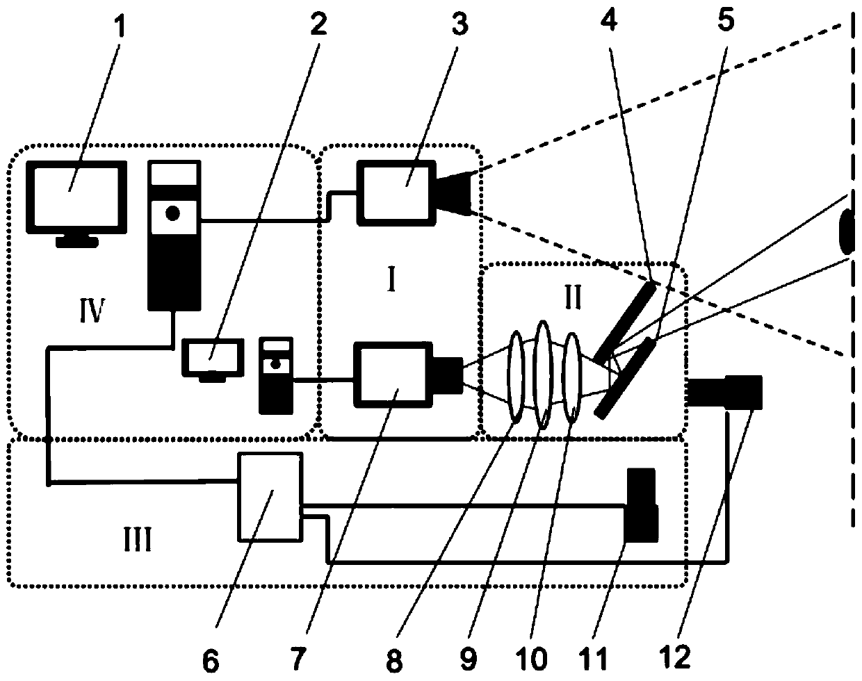
[0047] Such as figure 1 As shown, a visual tracking system provided by an embodiment of the present invention includes an image acquisition device I, an optical path conversion device II, and an optical path adjustment device III, wherein the image acquisition device includes a first camera 3 and a second camera with relatively fixed positions 7. The first camera 3 is used to acquire images in ...


PUM


Abstract

The invention belongs to the field of visual tracking and discloses a visual tracking system and method. The system comprises an image acquisition device, a light path conversion device and a light path adjustment device. The image acquisition device comprises a first camera and a second camera which are fixed in relative positions, and the first camera is used for acquiring an image and performing visual tracking to predict the position of a to-be-tracked target. The light path conversion device is arranged between the to-be-tracked target and the second camera and is used for clearly imagingthe to-be-tracked target on the second camera. The light path adjusting device adjusts the light path of the light path conversion device in real time according to the position of the to-be-tracked target, so that the target is always located at the imaging center of the second camera. The visual tracking method comprises the following steps: obtaining each frame of image by using a first cameraand carrying out visual tracking to predict the position of a target in each frame of image; and adjusting a light path in real time according to the position of the target to clearly image the targetat the center of the second camera. The method has the advantages of high speed, high robustness, good adaptability and the like.

Description

technical field [0001] The invention belongs to the field of visual tracking, and more particularly relates to a visual tracking system and method. Background technique [0002] With the rapid development of computer vision and machine vision technology, artificial intelligence has changed from the simple pursuit of accuracy in the past to the current situation of equal emphasis on accuracy, robustness and real-time performance. Only in this way can the rapid implementation of technology be accelerated. As one of the popular research directions of computer vision, visual tracking can not only be used as a part of complex technologies such as behavior recognition and video target detection, but also can be widely used in daily life and production as a separate technology, such as industrial robots, intelligent Security and unmanned driving and other fields. [0003] Visual tracking refers to the position of the target in the first frame and a video sequence, and it is requir...

Claims


Application Information

Patent Timeline
Patent Type & Authority Applications(China)
IPC IPC(8): H04N5/225H04N5/232
CPCH04N23/55H04N23/69
Inventor 杨华刘陈义宋开友李俊逸卢锦
Owner HUAZHONG UNIV OF SCI & TECH
Why Eureka
Try Eureka