Instrument cleaning device for gynecology

A cleaning device and device technology, applied in the field of medical devices, can solve the problems of inability to reverse the device, incomplete cleaning, etc., and achieve the effect of firm fixation, thorough cleaning, and prevention of cross-contamination

Inactive Publication Date: 2019-09-13
战治家
View PDF0 Cites 0 Cited by
  • Summary
  • Abstract
  • Description
  • Claims
  • Application Information

AI Technical Summary

Problems solved by technology

[0003] The instruments commonly used in gynecological diseases often need to be cleaned every time they are used. However, the existing devices cannot reverse the instruments during cleaning, resulting in incomplete cleaning. Therefore, a gynecological instrument cleaning device is proposed to solve the above problems

Method used


Image

  • Instrument cleaning device for gynecology
  • Instrument cleaning device for gynecology
  • Instrument cleaning device for gynecology

Examples


Embodiment 1

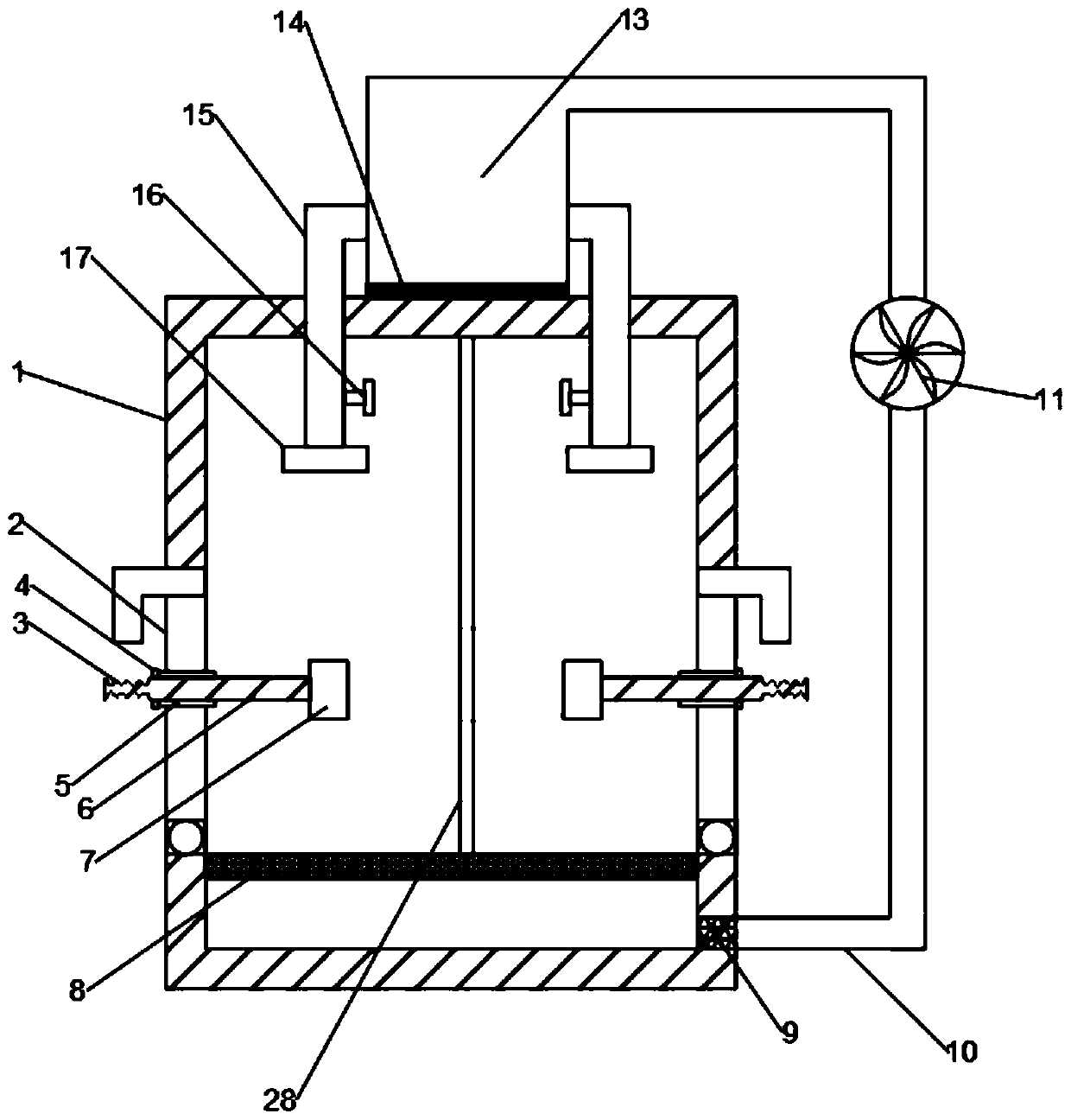
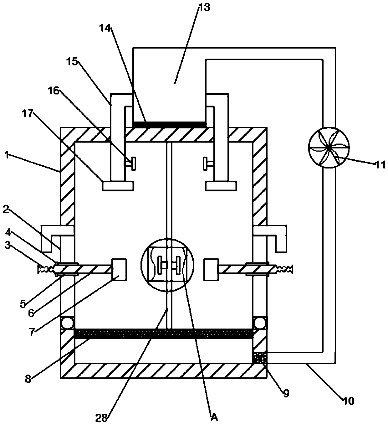
[0023] see figure 1 and image 3 , in an embodiment of the present invention, a gynecological instrument cleaning device includes a device main body 1, a hinged door 2, a rotating device 3, a clamping mechanism 7 and a water tank 13, and a fixed connection is provided in the middle of the top of the device main body 1 A water tank 13, the inside of the water tank 13 is provided with a heating device 14, which is used to heat the water in the water tank 13, so that the cleaning effect is better, and the left and right ends of the water tank 13 are symmetrically provided with connected second water pipes 15. The second water pipe 15 is "L" shape, and the lower end of the second water pipe 15 runs through the top of the device main body 1 and is provided with a water spray hole 17 above the inside of the device main body 1, through which the water spray hole 17 can drop water and spray the place, while the second water pipe 15 The second water pipe 15 is also provided with a val...

Embodiment 2

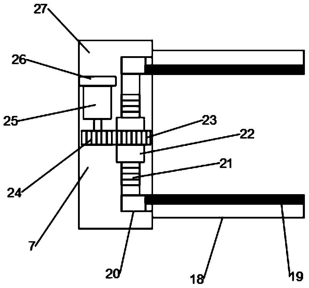
[0031] see Figure 2-4The difference between embodiment 2 and embodiment 1 is that it also includes a drying mechanism 12, the drying mechanism 12 is arranged on the splint 18 and is at the same height as the rotating device 3, and the drying mechanism 12 includes a heating wire 1201, a fan 1202 There are two fans 1202, and the fans 1202 are fixedly connected to the partition plate 28. The other end of the fans 1202 is arranged on the heating wire 1201, and the heating wire 1201 cooperates with the fan 1202 to realize rapid drying.

[0032] The working principle of the present invention is: the slider 20 penetrates the main body 1 of the device and is fixedly connected with the splint 18, the opposite surfaces of the two splints 18 are provided with rubber pads 19, which can protect the equipment when the friction force is increased, and the motor 25 works to drive The second gear 24 rotates, the first gear 23 drives the first gear 23 to rotate, thereby realizing the rotation ...


PUM


Abstract

The invention discloses an instrument cleaning device for gynecology, and relates to the technical field of medical instruments. The instrument cleaning device mainly solves the problem that instruments for gynecology are inconvenient to clean, and comprises a device body, hinged doors, a rotating device, a clamping mechanism and a water tank; the water tank which is fixedly connected is arrangedin the middle of the top of the device body, the hinged doors are symmetrically arranged on the left wall and the right wall of the device body, and the middles of the hinged doors are rotationally connected to the rotating device through bearings; and the clamping mechanism is arranged at the end, inside the device body, of the rotating device. According to the instrument cleaning device for gynecology, instruments for gynecology can be effectively fixed, meanwhile, fixing is firm, and the protection function can be achieved; meanwhile, the hinge doors are opened, then the clamping mechanismis used for clamping the to-be-cleaned instrument, and during cleaning, the rotating device is rotated manually so that multi-angle cleaning can be realized, and cleaning is more thorough; and the drying mechanism can be used for rapidly drying, the instrument can be rapidly used again, and cross contamination is avoided.

Description

technical field [0001] The invention relates to the technical field of medical instruments, in particular to an instrument cleaning device for gynecology. Background technique [0002] Medical devices refer to instruments, equipment, utensils, in vitro diagnostic reagents and calibrators, materials, and other similar or related items that are directly or indirectly used on the human body, including required computer software. The effectiveness of medical devices is mainly obtained through physical means, not through pharmacological, immunological or metabolic means, or although these means are involved, they only play an auxiliary role. The purpose of medical devices is the diagnosis, prevention, monitoring, treatment or mitigation of diseases; the diagnosis, monitoring, treatment, mitigation or functional compensation of injuries; the inspection, replacement, adjustment or support of physiological structures or physiological processes; the support or maintenance of life; P...

Claims


Application Information

Patent Timeline
Patent Type & Authority Applications(China)
IPC IPC(8): B08B3/10B08B3/02B08B3/14B08B13/00F26B21/00
CPCB08B3/02B08B3/10B08B3/14B08B13/00F26B21/00
Inventor 战治家许晓燕
Owner 战治家
Why Eureka
Try Eureka