Flat steel transverse curvature bending correcting machine

A curvature and flat steel technology, which is applied in the field of flat steel transverse curvature straightening machines, can solve problems such as poor correction efficiency and complex overall structure, and achieve the effects of reduced resistance, simple overall structure, and synchronous rotation distance adjustment

Pending Publication Date: 2019-09-13
太原太钢大明金属科技有限公司
View PDF0 Cites 2 Cited by
  • Summary
  • Abstract
  • Description
  • Claims
  • Application Information

AI Technical Summary

Problems solved by technology

[0002] In the production process of flat steel, side bending and plane bending will occur, so the transverse curvature needs to be corrected. The common straightening machine is composed of several driving rollers and driven rollers. For some larger size or strength When flat steel is used, the correction efficiency is poor, and multiple corrections are required
Therefore, people also set the driven roller to connect with the corresponding driving mechanism so that it can also actively rotate; and in the actual process, it is also necessary to adjust the distance between the upper and lower rollers to adapt to flat steel of different specifications, so that As a result, the overall structure is more complicated, and a large number of couplings need to be set

Method used


Image

  • Flat steel transverse curvature bending correcting machine
  • Flat steel transverse curvature bending correcting machine
  • Flat steel transverse curvature bending correcting machine

Examples


Embodiment Construction

[0023] The following describes the technical solutions in the embodiments of the present invention clearly and completely. Obviously, the described embodiments are only a part of the embodiments of the present invention, rather than all the embodiments. Based on the embodiments of the present invention, all other embodiments obtained by those of ordinary skill in the art without creative work shall fall within the protection scope of the present invention.

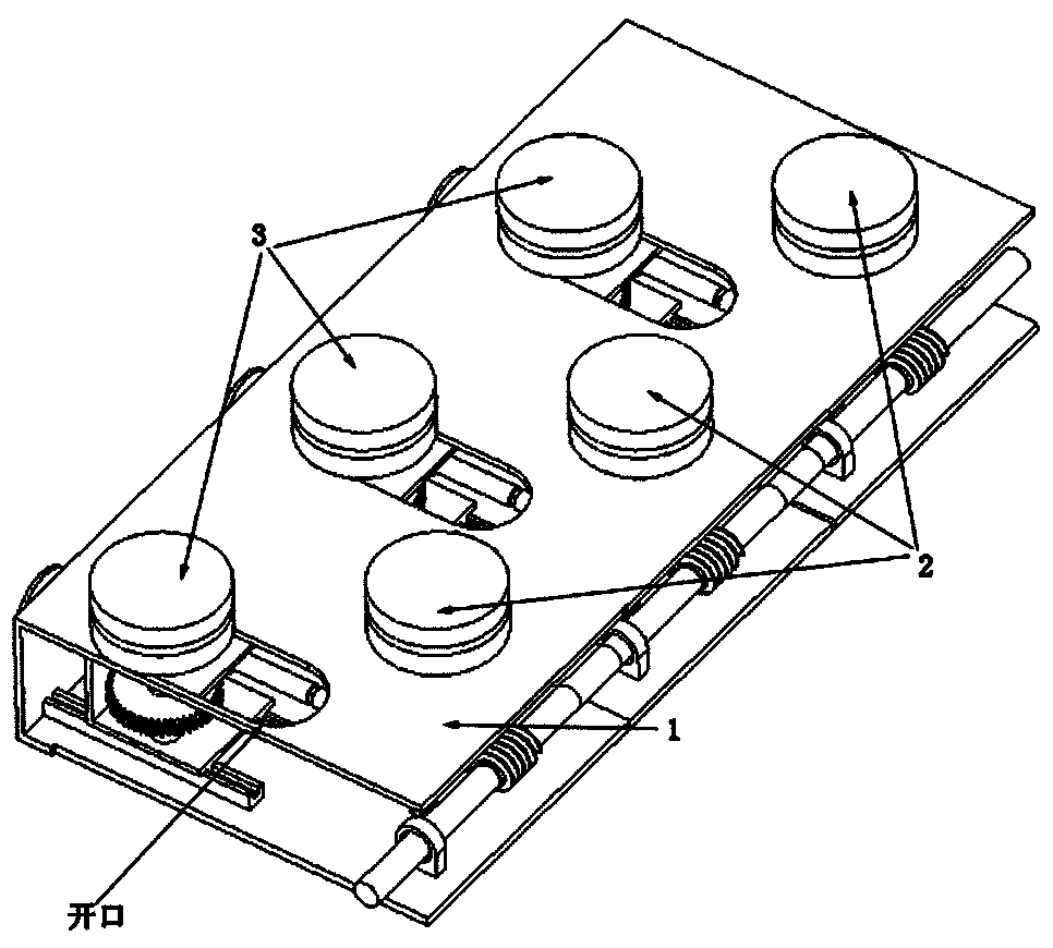
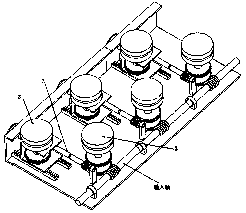
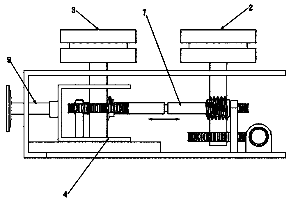
[0024] Such as Figure 1 to 5 As shown, a flat steel transverse curvature straightening machine includes a frame 1, a fixed straightening wheel 2 and an adjusting straightening wheel 3. The fixed straightening wheel 2 is rotatably connected with the frame 1, and the adjusting straightening wheel 3 passes through sliding The base 4 is connected with the frame 1, the sliding base 4 is slidingly connected with the frame 1, and the adjusting straightening wheel 3 is connected with the sliding base 4 in rotation.

[0025] Adjust th...


PUM


Abstract

The invention belongs to the technical field of straightening machines, and particularly relates to a flat steel transverse curvature bending correcting machine. A rack, a fixed straightening wheel and an adjusting straightening wheel are included; the fixed straightening wheel is rotationally connected with the rack; the adjusting straightening wheel is connected with the rack through a sliding base; the sliding base is in sliding connection with the rack; the adjusting straightening wheel is rotationally connected with the sliding base; the adjusting straightening wheel is connected with a first gear; the fixed straightening wheel is connected with a second gear; the first gear and the second gear are connected through a gear shaft; the two ends of the gear shaft are provided with transmission gears engaged with the first gear and the second gear; the gear shaft is a telescopic shaft; an adjusting screw is in threaded connection with the rack; one end of the adjusting screw is rotationally connected with the sliding base; and the adjusting screw is rotated so that the sliding base can be driven to move, and the distance between the adjusting straightening wheel and the fixed straightening wheel is adjusted. Due to the fact that the gear shaft is the telescopic shaft, when the sliding base and the adjusting straightening wheel on the sliding base move, synchronous rotating canstill be achieved. The integrated structure is simple, and the purposes of synchronous rotating and distance adjusting can be achieved.

Description

Technical field [0001] The invention belongs to the technical field of straightening machines, and particularly relates to a flat steel transverse curvature straightening machine. Background technique [0002] In the production process of flat steel, side bends and plane bends are generated, so it is necessary to correct the transverse curvature. The common straightening machine is composed of several driving rollers and driven rollers. For some size or strength In the case of flat steel, the correction efficiency is poor, and multiple corrections are required. Therefore, the driven roller is also connected to the corresponding driving mechanism, so that it can also actively rotate; and in the actual process, it is also necessary to adjust the distance between the upper and lower rollers to adapt to different specifications of flat steel. As a result, the overall structure is relatively complicated, and a large number of couplings are required. Summary of the invention [0003] ...

Claims


Application Information

Patent Timeline
IPC IPC(8): B21D1/02
CPCB21D1/02
Inventor 贾斌李哲玉李王军侍万家郭斌
Owner 太原太钢大明金属科技有限公司
Why Eureka
Try Eureka