Heat sink of electrolytic tank

A cooling device and electrolytic cell technology, applied in the electrolytic process, electrolytic components, cells, etc., can solve the problems that the concentration of sodium hypochlorite solution cannot be well controlled, the flow rate of cooling water cannot be controlled, and the temperature stability of the electrolytic cell is unfavorable. The effect of simple structure, good product quality and stable electrolysis rate

Active Publication Date: 2019-09-13
贵州成黔科技开发有限公司
View PDF8 Cites 3 Cited by
  • Summary
  • Abstract
  • Description
  • Claims
  • Application Information

AI Technical Summary

Problems solved by technology

Although this solution can adjust the temperature of the electrolytic cell, its structure is complicated. The temperature control method is to intermittently feed or disconnect the cooling water, which cannot control the flow of the cooling water. When the cooling water is fed, the temperature in the electrolytic cell It will drop suddenly. When the cooling water is disconnected, the temperature of the electrolytic cell will suddenly rise. This cooling method is also not conducive to the stability of the temperature in the electrolytic cell, and cannot keep the temperature in the electrolytic cell within a certain range. The concentration of sodium hypochlorite solution produced in the same time is still not well controlled

Method used


Image

  • Heat sink of electrolytic tank
  • Heat sink of electrolytic tank
  • Heat sink of electrolytic tank

Examples


Embodiment 1

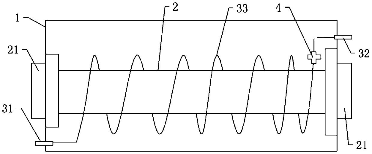
[0028] Embodiment one, such as figure 1 As shown, a cooling device for an electrolytic cell includes an electrolytic cell 1, an electrode assembly 2, a cooling mechanism and a temperature control mechanism 4. The electrolytic cell 1 is in a tubular shape, and the electrolytic cell 1 is filled with diluted brine. The connecting piece 21, the electrode assembly 2 is arranged in the electrolytic tank 1, the electrode assembly 2 includes a cathode plate and an anode plate, and the cathode plate and the anode plate are respectively connected with the conductive connecting pieces 21 at both ends of the electrolytic tank 1. The cooling mechanism includes a cooling pipe 33, a cooling water inlet 31 and a cooling water outlet 32, the cooling water inlet 31 and the cooling water outlet 32 ​​are respectively arranged on the two end side walls of the electrolytic cell 1, the cooling pipe 33 is immersed in the diluted brine and the cooling pipe 33 It is evenly wrapped around the electrode ...

Embodiment 2

[0034] Embodiment 2 differs from Embodiment 1 in that: the cooling pipe 33 is arranged above the electrode assembly 2 in an S shape, and the temperature generated during electrolysis makes the water body heat up and flows upward, so that the temperature of the water body above the electrode assembly 2 is high. For the temperature of the water body below the electrode assembly 2 , it is beneficial to improve the heat exchange efficiency to arrange the cooling pipe 33 above the electrode assembly 2 .

Embodiment 3

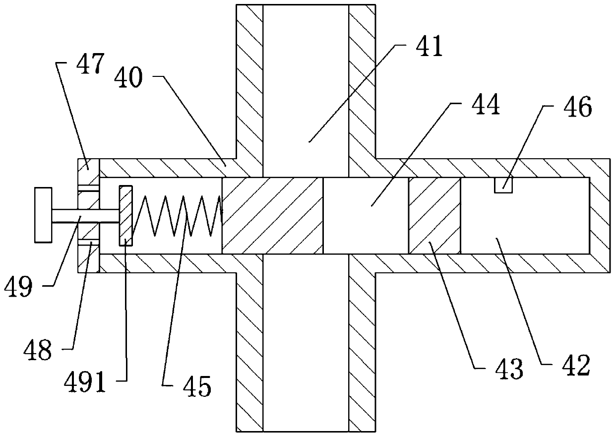
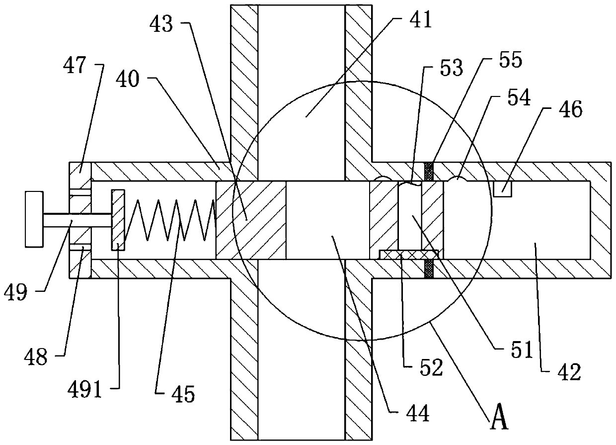
[0035] The third embodiment differs from the first embodiment in that: image 3 with Figure 4 As shown, in the slider body of the slider 43 close to the end of the stop block 46, a vertical through hole 51 that penetrates the slider 43 up and down is provided, and the bottom of the vertical through hole 51 is provided with a plug to block the bottom of the vertical through hole 51. In the heating block 52, the upper end of the vertical through hole 51 is provided with an elastic film 53 that blocks the upper end of the vertical through hole 51, and a heat insulating sheet 55 is provided along the circumference of the body of the slideway near the end of the limit block 46.

[0036] When the temperature in the electrolytic cell rises, the temperature of the inner chamber of the slideway near the end of the limit block 46 rises, causing the air pressure in the inner chamber to increase, and the pressure generated by the increased air pressure on the slider 43 makes the slider 4...


PUM


Abstract

The invention specifically relates to a heat sink of an electrolytic tank, belonging to the technical field of electrolysis of sodium hypochlorite. The heat sink comprises the electrolytic tank, an electrode assembly, a cooling mechanism and a temperature controlling mechanism. The cooling mechanism comprises a cooling pipe immersed in brine; one end of the cooling pipe is connected with a coolingwater inlet, and the other end of the cooling pipe is connected with a cooling water outlet; the temperature controlling mechanism is connected with the cooling pipe in series and comprises a body which has a flow channel running through the body; two ends of the flow channel communicate with the cooling pipe; the body is further provided with a slideway which perpendicularly intersects with andcommunicates with the flow channel, a slide block is arranged in and slidably connected with a slideway; a flow hole cooperating with the flow channel is formed in the slide block; one end of the slideway is provided with a compression spring that abuts against the slide block; and the other end of the slideway is provided with a stop block. The heat sink of the invention carries out real-time adjustment of the temperature of the electrolytic tank, so the temperature of the electrolytic tank is always maintained in a stable range; and thus, an electrolysis rate is stable, and the concentrationfluctuation of a produced sodium hypochlorite solution is small.

Description

technical field [0001] The invention relates to the technical field of sodium hypochlorite electrolysis, in particular to a cooling device for an electrolytic cell. Background technique [0002] Sodium hypochlorite is a strong oxidant with good disinfection and bleaching functions, and it is usually prepared by electrolysis. The electrolytic cell is one of the main equipment for the preparation of sodium hypochlorite by electrolysis. Put dilute brine into the electrolytic cell, connect the cathode and anode DC power supply through the silicon rectifier, and carry out oxidation-reduction reaction under the action of the current to generate sodium hypochlorite and other corresponding substances. Due to the oxidation-reduction When the reaction will generate a lot of heat, the temperature of the solution in the electrolytic cell will rise, which will lead to an increase in the temperature of the electrolytic solution in the electrolytic cell, resulting in an increase in the rat...

Claims


Application Information

Patent Timeline
Patent Type & Authority Applications(China)
IPC IPC(8): C25B15/00C25B9/00C25B1/26
CPCC25B1/265C25B9/00C25B15/00
Inventor 王忠祥
Owner 贵州成黔科技开发有限公司
Why Eureka
Try Eureka