Overflowing-pipe-containing saline-alkali region water resource collecting and utilizing system

An overflow pipe and water resource technology, applied in waterway systems, applications, water supply devices, etc., can solve the problems of large amount of greening earthwork, uneconomical, eutrophication of downstream water bodies, etc. The effect of reducing the amount of earthwork

Inactive Publication Date: 2019-09-13
天津生态城市政景观有限公司
View PDF0 Cites 0 Cited by
  • Summary
  • Abstract
  • Description
  • Claims
  • Application Information

AI Technical Summary

Problems solved by technology

However, the disadvantage of the existing method of "flooding with stone chips" and "salt drainage through hidden pipes" to control saline-alkali land is that after the rainwater infiltrates into the soil, it enters the saline-alkali layer through the stone chip layer, or is directly discharged into the municipal water. Drainage pipe network, rainwater cannot be effectively used, and at the same time, a large amount of nutrients such as nitrogen, phosphorus, and potassium are also discharged into the municipal rainwater system during the fertilization process, which also causes eutrophication of downstream water bodies; surface runoff that does not have time to infiltrate during rainfall Rainwater flows into low-potential areas such as surrounding roads, which increases road drainage pressure and waterlogging risk. At the same time, the green land soil washes the road surface with the runoff, causing runoff pollution such as mud left on the road after rain; the amount of land for greening is large and uneconomical

Method used


Image

  • Overflowing-pipe-containing saline-alkali region water resource collecting and utilizing system
  • Overflowing-pipe-containing saline-alkali region water resource collecting and utilizing system

Examples


Embodiment Construction

[0021] In order to illustrate the present invention more clearly, the following further describes the present invention in combination with preferred embodiments. Those skilled in the art should understand that the content described below is illustrative rather than restrictive, and should not limit the protection scope of the present invention.

[0022] It should be noted that when an element is referred to as being "fixed to" or "disposed on" another element, it can be directly on the other element or indirectly on the other element. When an element is said to be "connected to" another element, it can be directly connected to the other element or indirectly connected to the other element.

[0023] It should be understood that the terms "length", "width", "upper", "lower", "front", "rear", "left", "right", "vertical", "horizontal", "top" The orientation or positional relationship indicated by "bottom", "inner", "outer", etc. is based on the orientation or positional relationship ...


PUM


Abstract

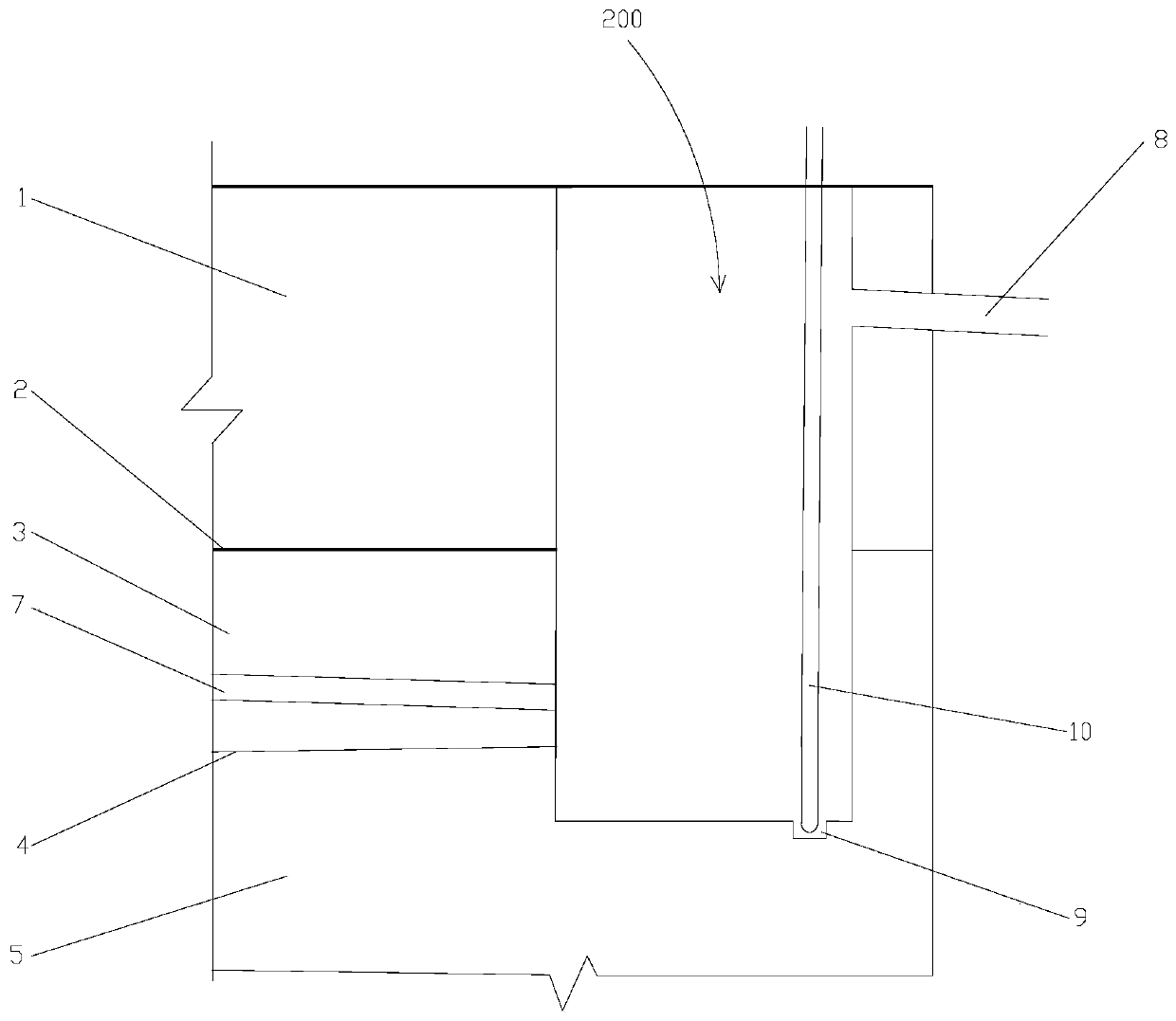
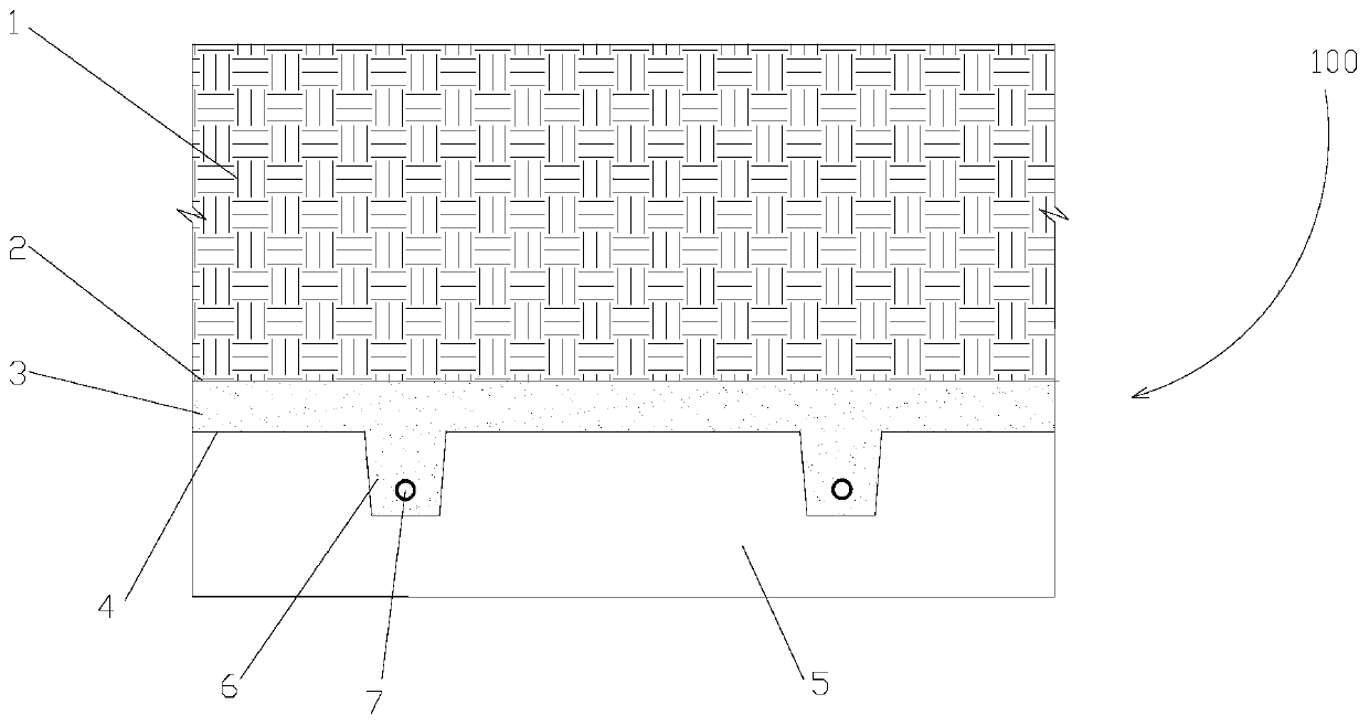
The invention discloses an overflowing-pipe-containing saline-alkali region water resource collecting and utilizing system, which comprises a soil body and storage and drainage wells. The soil body comprises a planting soil layer, a permeable membrane layer, a water storage layer, waterproof layers and a saline-alkali soil layer which are sequentially arranged from top to bottom; a trench protruding into the saline-alkali soil layer is formed in the lower surface of the water storage layer and internally provided with a concealed conduit; the concealed conduit is connected and communicates with the storage and drainage wells in the slope direction; the storage and drainage wells are formed in the soil body at intervals, the depths of the storage and drainage wells extend to the lower partof the trench from top to bottom, well walls of the parts, making contact with the water storage layer, of the storage and drainage wells are each of a permeable pipe structure, and well walls of other parts are each of an impermeable structure; overflowing drainage pipes are arranged on the walls of the storage and drainage wells, and the horizontal height of the overflowing drainage pipes is atthe depth of 20-50 cm of the planting soil layer; and junctions of the system and surrounding buildings or structures are inversely packed through the lateral waterproof layers. Rainwater permeating into the planting soil layer after precipitation can be effectively collected, and salt return of the saline-alkali soil layer to the planting soil layer is avoided.

Description

Technical field [0001] The invention belongs to the field of saline-alkali water treatment, and particularly relates to a saline-alkali water collection and utilization system containing an overflow pipe. Background technique [0002] Rainwater is a very precious freshwater resource, especially for coastal saline-alkali land. In such severely water-deficient areas, collecting and using rainwater is even more precious. Due to lack of water in saline-alkali land, the salt concentration in the soil exceeds the plant's ability to withstand it, causing salt damage. Salt comes with water, and salt goes with water, so an adequate supply of fresh water resources must be ensured so that saline-alkali land resources can be used sustainably. [0003] The total area of ​​coastal saline-alkali soil in my country reaches 500×10 4 hm 2 ,. In recent years, with the development of economy and industry, saline-alkali areas have become a new position for economic development. In order to meet the n...

Claims


Application Information

Patent Timeline
Patent Type & Authority Applications(China)
IPC IPC(8): E02B11/00E03F5/10A01B79/00
CPCA01B79/00E02B11/005E03F5/10
Inventor 周国华王志刚李忠锋张勇任娜卢立波刘玮马莎莎
Owner 天津生态城市政景观有限公司
Why Eureka
Try Eureka