
Hydraulically controlled two-way reversing valve, load holding module and load holding system

A load-holding, reversing valve technology, applied in multi-way valves, valve devices, valve details, etc., can solve problems such as pipe bursting, poppet valve core breakage, inaccurate positioning, etc., and achieve the effect of simple control

Pending Publication Date: 2019-09-13
XCMG CONSTR MACHINERY
View PDF0 Cites 3 Cited by
  • Summary
  • Abstract
  • Description
  • Claims
  • Application Information

AI Technical Summary

Problems solved by technology

[0009] Option 3 is not suitable for hydraulic systems with frequent movements. When the load is large enough, the hydraulic lock may not be opened, nor can it be positioned accurately, and it is prone to pipe bursts! For the one-way hydraulic lock with pilot control, the frequent opening and closing of the small poppet spool under high pressure may easily cause the poppet spool to break

Method used


Image

  • Hydraulically controlled two-way reversing valve, load holding module and load holding system
  • Hydraulically controlled two-way reversing valve, load holding module and load holding system
  • Hydraulically controlled two-way reversing valve, load holding module and load holding system

Examples


Embodiment 1

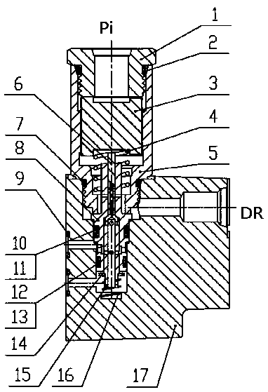
[0043] to combine figure 1 As shown, a hydraulically controlled two-way reversing valve, the end cover 17 is square, the upper end surface of the end cover 17 is provided with a vertically downward step installation hole, and the left side of the end cover 17 is provided with an oil passage connected to the step installation hole a. Oil passage b, the right side of the end cover 17 has an oil passage DR connected to the step mounting hole.

[0044] The lower end of the valve body Ⅰ5 is provided with external threads, and the outer end of the stepped mounting hole of the end cover 17 is provided with external threads. An O-ring III7 is installed between the bodies I5. A stepped hole is opened at the center of the valve body I5, and a valve seat 1 and a cover gasket 3 are installed in sequence from outside to inside in the stepped hole of the valve body I5. The shaft center of the valve seat 1 is provided with an oil passage Pi passing through the valve seat 1. The lower end ...

Embodiment 2

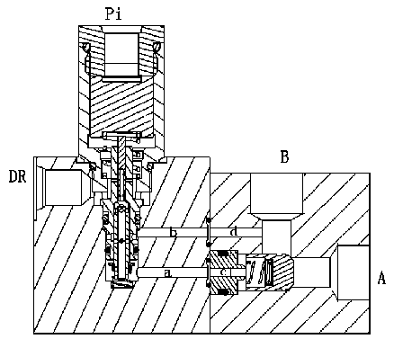
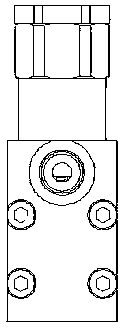
[0049] On the basis of the first embodiment above, combined with Figure 2 to Figure 4 As shown, the load holding module is mainly composed of a hydraulically controlled two-way reversing valve and a holding valve.

[0050] The holding valve includes a square body II18. There are oil passages c and d on the left side of valve body II18, oil passage B is opened on the upper side of valve body II18, and oil passage A is opened on the right side of valve body II18. The inner end of oil passage d is connected with the middle part of oil passage B, and the inner ends of oil passage c, oil passage A and oil passage B intersect.

[0051] Oil passage c is a stepped hole, and cover plate 21, spring III 20, and retaining spool 19 are installed sequentially in oil passage c from outside to inside. The circumferential surface of the cover plate 21 is connected with the inner wall of the oil passage c, and the circumferential surface of the cover plate 21 is provided with a mounting groo...

Embodiment 3

[0054] On the basis of the above-mentioned embodiment two, combining Figure 5 As shown, the load holding system includes a load holding module, a multi-way valve and a boom cylinder. The A1 port of the multi-way valve is connected to the oil passage A of the load holding module; the oil passage B of the load holding module is connected to the large chamber of the boom cylinder, the oil passage DR of the load holding module is connected to the fuel tank, and the oil passage Pi of the load holding module is connected to the multi-channel The pilot pressure oil passage of the lower position of the valve; the small cavity of the boom cylinder is connected to the B1 oil port of the multi-way valve.

[0055] Lifting condition of the boom cylinder:

[0056] The boom cylinder rises, that is, the rising position of the multi-way valve gives pilot pressure, the principle of the multi-way valve moves to the right, and the pressure oil flows from the P port of the multi-way valve throug...


PUM


Abstract

The invention provides a hydraulically controlled two-way reversing valve, a load holding module and a load holding system and belongs to the technical field of hydraulic systems of engineering machinery. An oil port A of a multitandem valve is connected to an oil duct A of the load holding module; an oil duct B of the load holding module is connected to a large cavity of an oil cylinder of a movable arm, an oil duct DR of the load holding module is connected to an oil tank, and an oil duct Pi of the load holding module is connected to a descending position pilot pressure oil duct of the multitandem valve; and a small cavity of the oil cylinder of the movable arm is connected to an oil port B1 of the multitandem valve. As the area ratio of a cap nut gasket and a pilot valve element in thehydraulically controlled two-way reversing valve can reach 1: 64, the hydraulically controlled two-way reversing valve is simple and convenient to operate. By means of a holding function of a holdingvalve, an inner revealing amount can be controlled at zero, so that the load can be held in a constant position rather than be decreased along with change of time; a pilot effect is exerted to the holding valve through the hydraulically controlled two-way reversing valve, so that a small cone valve element acts frequently under a pilot pressure without phenomena such as breakage.

Description

technical field [0001] The invention relates to the technical field of construction machinery hydraulic systems, in particular to a hydraulically controlled two-way reversing valve, a load holding module and a load holding system, which are used for the load holding of an actuator. Background technique [0002] Construction machinery has a wide range of uses, and different uses and complex working conditions determine the complexity of its hydraulic system. The actuators of many hydraulic systems are required to remain constant at a certain position, and the following solutions are common: [0003] 1. For the hydraulic system that requires high-end and precision, it is realized through a balance valve; [0004] 2. Control the matching gap between the valve stem and the valve core of the multi-way valve, and realize it by using the median function of the multi-way valve; [0005] 3. A hydraulic lock is added to the actuator. [0006] In actual working conditions, it is fou...

Claims


Application Information

Patent Timeline
Patent Type & Authority Applications(China)
IPC IPC(8): F15B13/02F16K27/08F16K11/044F16K27/02
CPCF15B13/021F16K27/08F16K11/044F16K27/0263
Inventor 乔战战谢朝阳张安民孙志远陈素芹
Owner XCMG CONSTR MACHINERY
Learn More