Glass taking and placing mechanism

A glass and lifting mechanism technology, applied in the field of glass pick-and-place mechanism, can solve problems such as equipment performance or appearance damage, and achieve the effect of improving safety

Pending Publication Date: 2019-09-13
杨少宏
View PDF0 Cites 7 Cited by
  • Summary
  • Abstract
  • Description
  • Claims
  • Application Information

AI Technical Summary

Problems solved by technology

This method is undoubtedly more violent, and it is easy to damage the device and cause damage to the performance or appearance of the device.

Method used


Image

  • Glass taking and placing mechanism
  • Glass taking and placing mechanism
  • Glass taking and placing mechanism

Examples


Embodiment 1

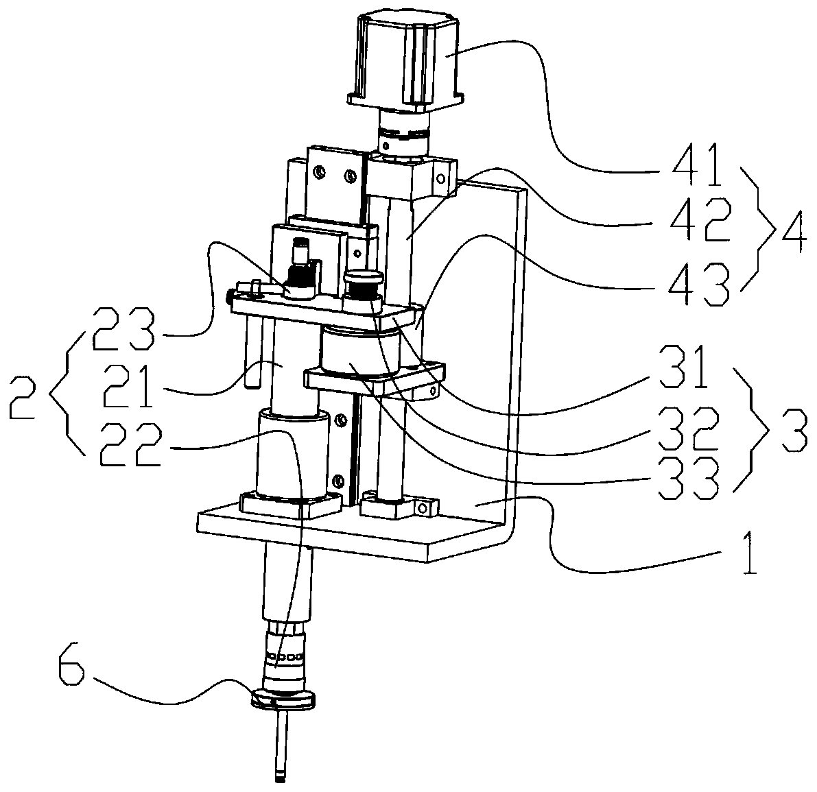
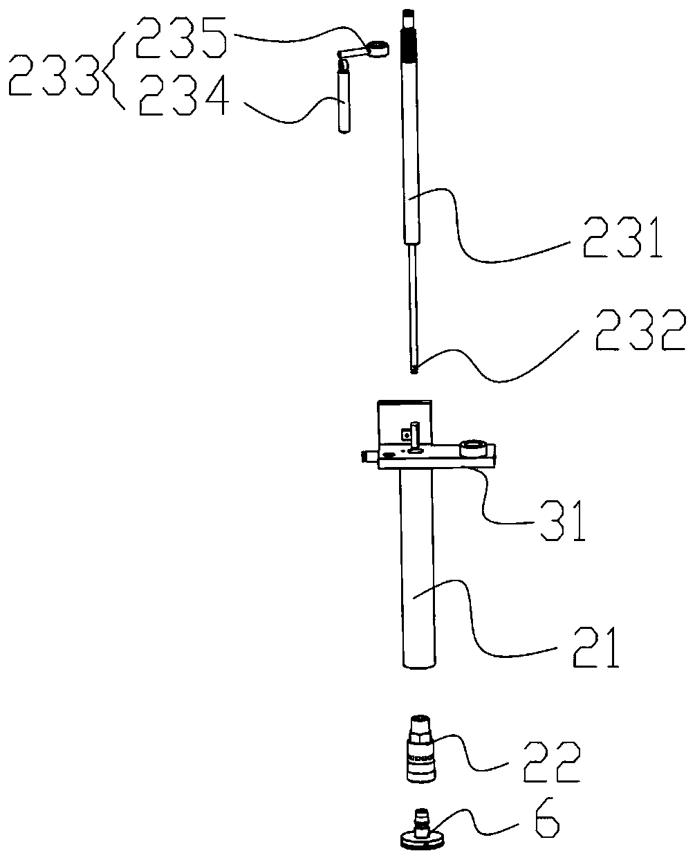
[0026] Such as figure 1 As shown, this embodiment provides a glass pick-and-place mechanism, including a base 1, an air guiding mechanism 2, a buffer mechanism 3, a lifting mechanism 4 and a suction cup 6 for sucking glass, and the lifting mechanism 4 is arranged on the The base 1, the lifting mechanism 4 is used to drive the air guiding mechanism 2 to lift, the gas guiding mechanism 2 is connected to the output end of the lifting mechanism 4 through the buffer mechanism 3, and the buffer mechanism 3 is used for Absorb the impact force between the suction cup 6 and the glass, thereby reducing the risk of the glass being crushed by the suction cup 6. The input end of the air guide mechanism 2 is used to connect an external air source, and the suction cup 6 is arranged on the air guide mechanism 2 output.

[0027] The present invention achieves the non-violent effect of removing the glass from the shell by changing the air pressure, specifically by sucking and pulling up the gl...

Embodiment 2

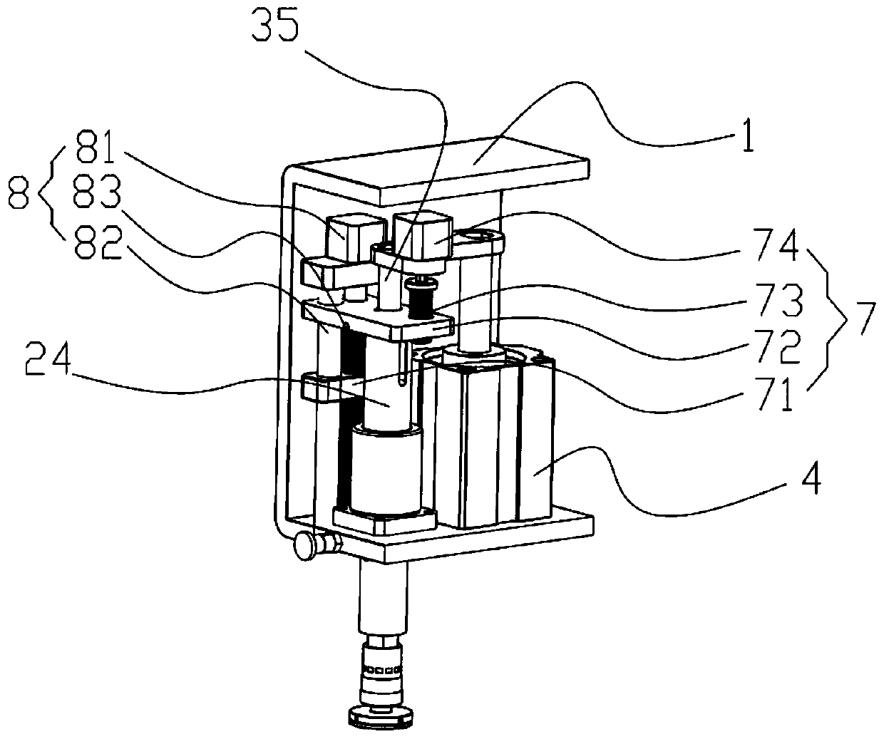
[0040] Such as image 3 with Figure 5 As shown, compared with Embodiment 1, this embodiment differs in the structure of the buffer mechanism 3 and the structure of the air guide mechanism 2, specifically: the air guide mechanism 2 is not provided with an inner air guide mechanism 23, that is, the air guide mechanism 2 Including air guide sleeve 24, quick joint 22 and suction cup 6, suction cup 6 is installed on air guide sleeve 24 through quick joint 22, and the input end of air guide sleeve 24 (i.e. air inlet 242) is arranged on one side of air guide sleeve 24 On the side, the top of the air guide sleeve 24 is provided with a blind hole 241; the buffer mechanism 3 includes a force unloading member (not marked in the figure) and a pressure rod 35, and the pressure rod 35 and the air guide mechanism 2 are all arranged on The output end of the lifting mechanism 4, the force unloading member is arranged in the blind hole 241, the pressure rod 35 is movably assembled in the blin...


PUM


Abstract

The invention relates to the technical field of glass transportation, in particular to a glass taking and placing mechanism. The glass taking and placing mechanism comprises a base, an air guiding mechanism, a buffering mechanism, a lifting mechanism and a suction cup used for sucking glass; the lifting mechanism is arranged on the base; the lifting mechanism is used for driving the air guiding mechanism to ascend and descend; the air guiding mechanism is connected to the output end of the lifting mechanism through the buffering mechanism; the buffering mechanism is used for absorbing an impact force between the suction cup and the glass; and the input end of the air guiding mechanism is externally connected with an air source; and the suction cup is arranged at the output end of the air guiding mechanism. By changing an air pressure, specifically sucking and pulling up the glass by the suction cup, the effect of taking away the glass from a shell nonviolently is realized; and meanwhile, due to the arrangement of the buffering mechanism, it is guaranteed that the air guiding mechanism and the suction cup do not descend excessively to crush the glass, so that the safety of dismounting the glass is improved.

Description

technical field [0001] The invention relates to the technical field of glass transportation, in particular to a glass pick-and-place mechanism. Background technique [0002] For mobile phones, watches and other devices, in order to allow users to better view the screen, glass screens are generally used as screens. Since the above-mentioned equipment has tended towards the integration of the shell at present, that is to say, when this type of equipment breaks down, the glass can only be removed from the shell to carry out internal maintenance. [0003] However, in the prior art, the method of prying is generally adopted, that is, an external tool is used to pry open from the gap between the shell and the glass cover. This method is undoubtedly more violent, and it is easy to damage the device and cause damage to the performance or appearance of the device. Contents of the invention [0004] Aiming at the problems in the prior art, the invention provides a glass pick-and-p...

Claims


Application Information

Patent Timeline
Patent Type & Authority Applications(China)
IPC IPC(8): G04D3/06
CPCG04D3/067
Inventor 杨少宏苏钱艺杨灵曦杨竣麟
Owner 杨少宏
Why Eureka
Try Eureka