Connection device for hydraulic circuit

A technology for connecting devices and hydraulic circuits, applied in clutches, couplings, mechanical equipment, etc., to solve problems such as increasing the maximum pressure that can be supported

Inactive Publication Date: 2019-09-13
莱卡姆动力传动系统责任有限公司
View PDF6 Cites 0 Cited by
  • Summary
  • Abstract
  • Description
  • Claims
  • Application Information

AI Technical Summary

Problems solved by technology

Furthermore, it is not possible to increase the maximum pressure that can be supported, e.g. beyond 50 bar, without also increasing the stiffness of the pin and thus the assembly load

Method used


Image

  • Connection device for hydraulic circuit
  • Connection device for hydraulic circuit
  • Connection device for hydraulic circuit

Examples


Embodiment Construction

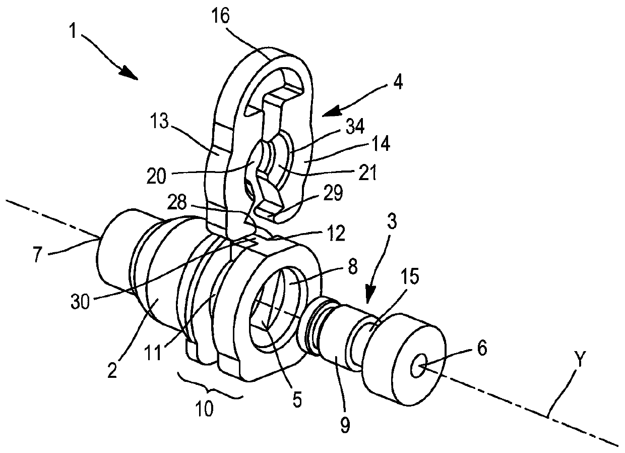
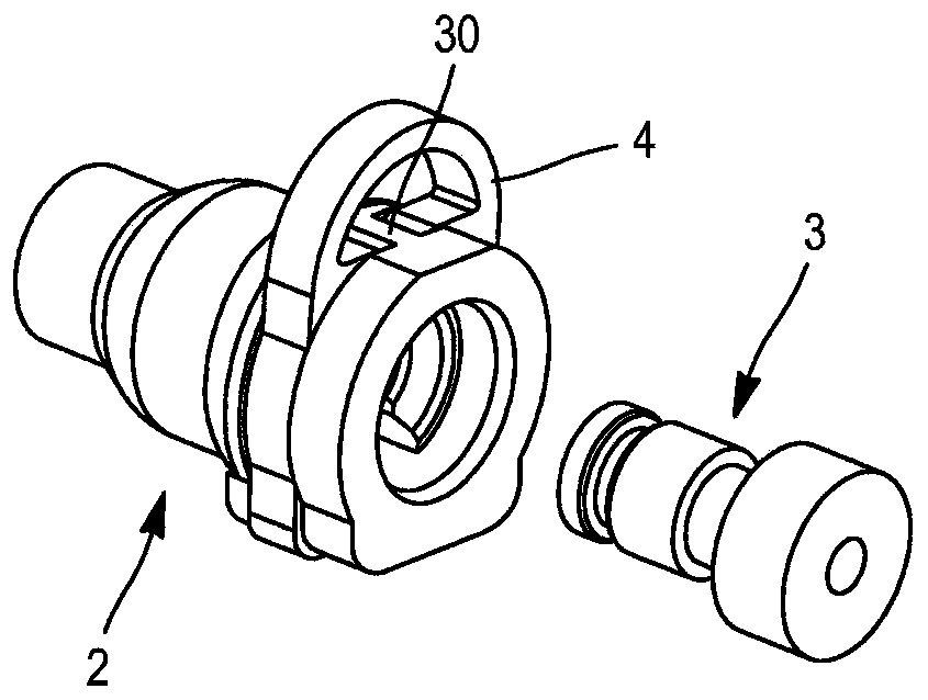
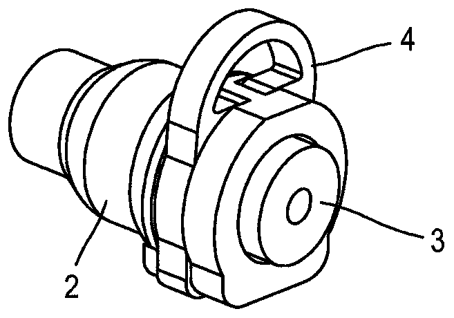
[0041] Figure 1 to Figure 3 Shown is a hydraulic circuit connection device intended to be integrated into a hydraulic system for controlling a motor vehicle clutch to connect two hydraulic conduits together.

[0042] Such as Figure 1 to Figure 3 As shown in , the connection device 1 has three main components: a female connector 2 , a male connector 3 and a locking clip 4 . The male connector 3 can be accommodated in the female connector 2 in the axial direction. The locking clip 4 is intended to keep the male connector 3 engaged in the female connector 2 .

[0043]The locking clip 4 has two arms 13 and 14 connected together by an elastic connecting portion 16 to form a substantially U-shape. The locking clip 4 is made of a single piece of plastic, such as polyamide 6-6, advantageously reinforced with glass fibres. When a force is exerted on the arms 13 and 14, the two arms 13 and 14 of the locking clip 4 can be elastically separated from each other to reach the separated...


PUM


Abstract

The invention relates to a connection device (1) for a hydraulic circuit, the device comprising: a female connector (2), the female connector having two fastening grooves (11, 12); a male connector (3), the male connector (3) having a notch (15) and being able to be inserted into the female connector; and a U-shaped locking clip having a first (13) and a second (14) arm that are connected by an elastic connecting portion (16), each of the two arms being inserted into one of the two grooves (11, 12) and being able to be spaced apart from one another elastically and the first and the second arm(13, 14) each having a frustoconical ramp (21) which is oriented such that, when the end piece (9) of the male connector is inserted into the female connector, said end piece of the male connector exerts on the ramp (21) a force that moves the two arms (13, 14) apart until at least one of the first and second arms is housed in the notch (15).

Description

technical field [0001] The invention relates to the field of hydraulic circuit connections, for example of a hydraulic circuit for actuating a clutch of a motor vehicle. Background technique [0002] In hydraulic circuits it is known to insert a male fitting into a female fitting in order to connect the two parts of the hydraulic circuit. [0003] In document FR2808071 is disclosed a feed connection comprising a tubular fitting inserted into a tubular feed inlet body. The tubular feed inlet body has two slots arranged in a transverse plane and leading to the inner duct of said body. The U-shaped metal pin has two arms inserted into one and the other of the two slots, respectively. The operator engages the fitting axially in the body. During this operation of engaging the fitting in the body, the two arms of the metal pin are deformed by moving away from each other and then fit into radial annular recesses arranged in the outer cylindrical surface of the fitting. Thus, th...

Claims


Application Information

Patent Timeline
Patent Type & Authority Applications(China)
IPC IPC(8): F16L37/088F16D48/02
CPCF16L37/0885
Inventor 克里斯托夫·莫里尔马西莫·西玛克里斯蒂亚诺·菲索雷阿莱西奥·普拉托伊戈尔·维科
Owner 莱卡姆动力传动系统责任有限公司
Why Eureka
Try Eureka