Traction device with buffer function for railway locomotive

A technology for railway locomotives and traction devices, applied in traction devices, railway car body parts, transportation and packaging, etc., can solve the problems of complex structure of self-locking devices, inability to use directly, poor applicability, etc., to reduce production difficulty and cost, Reduces friction and enhances stability

Active Publication Date: 2019-09-17
NANJING SHILAIER AUTOMOTIVE ELECTRONICS CO LTD
View PDF6 Cites 2 Cited by
  • Summary
  • Abstract
  • Description
  • Claims
  • Application Information

AI Technical Summary

Problems solved by technology

[0006] To sum up, the present invention provides a traction device with a buffer function for railway locomotives. Through the improvement of structure and functionality, in order to solve the problem of poor applicability, it is necessary to cooperate with corresponding traction devices after

Method used


Image

  • Traction device with buffer function for railway locomotive
  • Traction device with buffer function for railway locomotive
  • Traction device with buffer function for railway locomotive

Examples


Embodiment Construction

[0032] Embodiments of the present invention will be further described in detail below in conjunction with the accompanying drawings and examples. The following examples are used to illustrate the present invention, but should not be used to limit the scope of the present invention.

[0033] In the description of the present invention, unless otherwise stated, the meaning of "plurality" is two or more; the terms "upper", "lower", "left", "right", "inner", "outer" , "front end", "rear end", "head", "tail", etc. indicate the orientation or positional relationship based on the orientation or positional relationship shown in the drawings, and are only for the convenience of describing the present invention and simplifying the description, rather than Nothing indicating or implying that a referenced device or element must have a particular orientation, be constructed, and operate in a particular orientation should therefore not be construed as limiting the invention. In addition, t...


PUM


Abstract

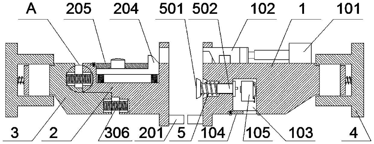
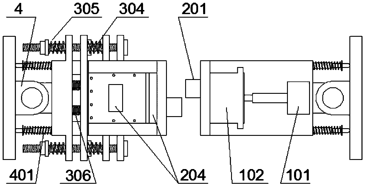
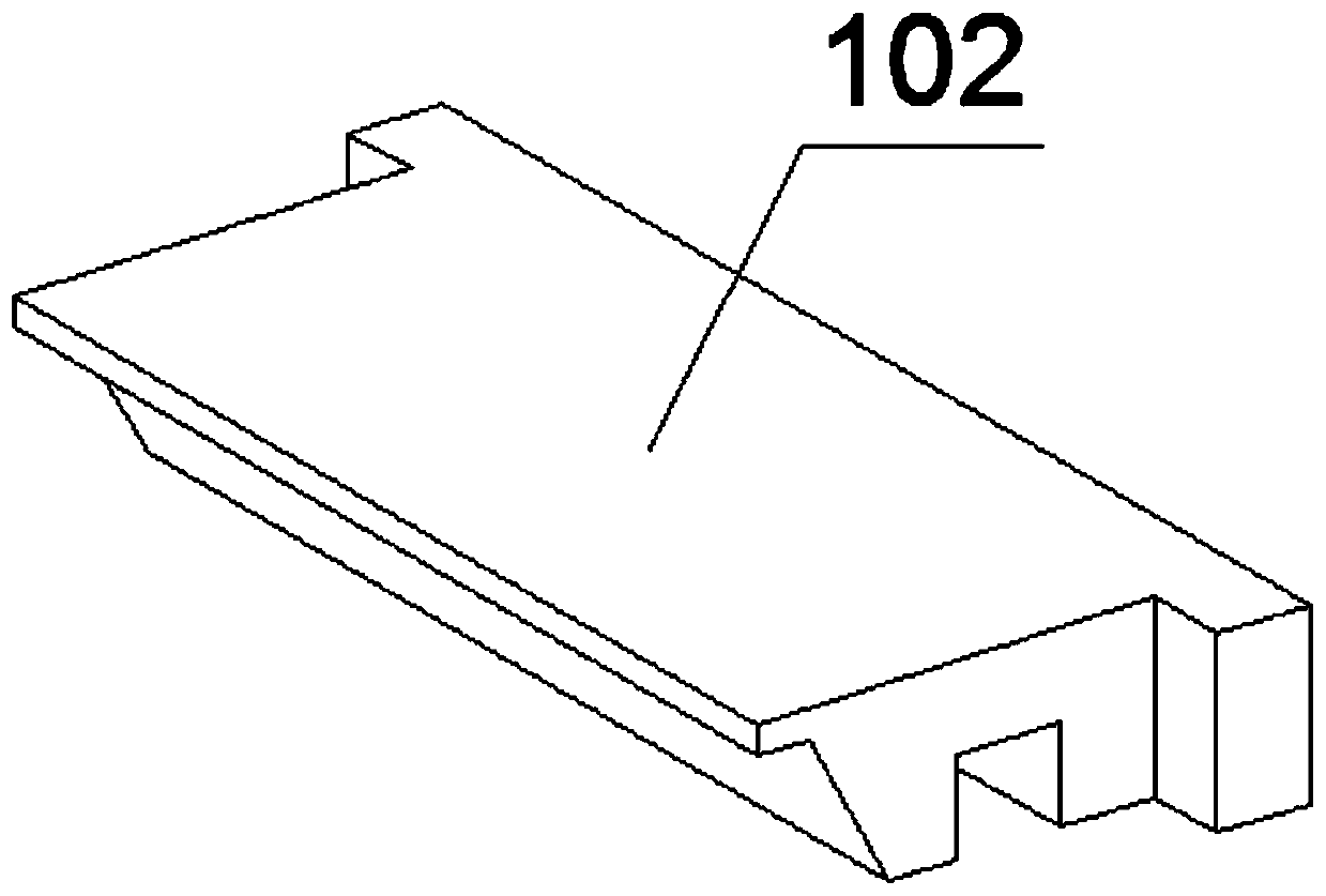
The invention provides a traction device with the buffer function for a railway locomotive. The traction device comprises a traction block A, an air cylinder, a locking block, a traction block B, a traction block C, shock absorption grooves, a T-shaped block, a T-shaped groove, springs A, round nuts, shock absorbers, a spring B, a touching device A and a touching device B; the top portion of the traction block A is provided with the air cylinder through a bolt, the top portion of the air cylinder is provided with a magnetic plate structure in an integrated mode, and the external side of the magnetic plate structure is fixedly provided with the locking block through adsorption; the top portions of the neighboring edges of the traction block A and the traction block B are correspondingly provided with guiding inserted holes, and the locking block is arranged in the guiding inserted hole of the top portion of the traction block A through the air cylinder; and through the arranged T-shaped block, the T-shaped groove and the shock absorbers, the stable and good buffer ability is provided for the traction device to buffer inertial impact force, and through dual arrangement and interlocking matching of the T-shaped block and the T-shaped groove, the buffered direction can be stable.

Description

technical field [0001] The invention relates to the technical field of trains, and more specifically relates to a traction device with a buffer function for a railway locomotive. Background technique [0002] The traction device is a device used to connect the two ends of the train wagon or locomotive. It has the functions of connection, traction and buffering. According to the development of society, its structure is also changing. The previous hook structure is gradually improved to a complex structure such as self-locking. , in the case of precise alignment of the train, it can be self-locked by moving the front of the car, and has high safety performance. [0003] Based on the above, the inventors found that the currently used traction device has poor applicability, and needs to be connected with the corresponding traction device after certain improvements on different models of trains, etc., and the self-locking device has a complex structure and high cost, and needs to...

Claims


Application Information

Patent Timeline
IPC IPC(8): B61G9/04B61G9/20
CPCB61G9/04B61G9/20
Inventor 戴圣洁
Owner NANJING SHILAIER AUTOMOTIVE ELECTRONICS CO LTD
Why Eureka
Try Eureka