A modular modular expansion device

A telescopic device and modular technology, applied in construction, bridge construction, bridges, etc., can solve the problems of difficult to ensure locking quality, narrow working space, difficult operation, etc., to achieve easy maintenance and handling, guarantee stability, low cost effect

Active Publication Date: 2021-10-26
成都天元智成科技有限公司
View PDF26 Cites 0 Cited by
  • Summary
  • Abstract
  • Description
  • Claims
  • Application Information

AI Technical Summary

Problems solved by technology

Although this technology has greatly improved the technical problems of post-failure maintenance and treatment compared with the above-mentioned integral modular expansion device, the sequential docking of two adjacent modular expansion device modules in this technology is through The "finger-joint" docking structure formed between the corresponding beam sections is realized. The assembly, docking, disassembly and separation need to be carried out on both sides of the "finger-joint" docking structure between the corresponding beam sections. The working space is very large. Narrow and narrow, especially when the bridge expands and the modular expansion device is in a contracted state. In a narrow operating space, the two sides of the "finger-joint" docking structure are locked or loosened. It has technical problems such as difficult operation and low efficiency, and what's more, it is difficult to ensure the quality of locking during assembly and docking, and there are potential safety hazards

Method used


Image

  • A modular modular expansion device
  • A modular modular expansion device
  • A modular modular expansion device

Examples


Embodiment 1

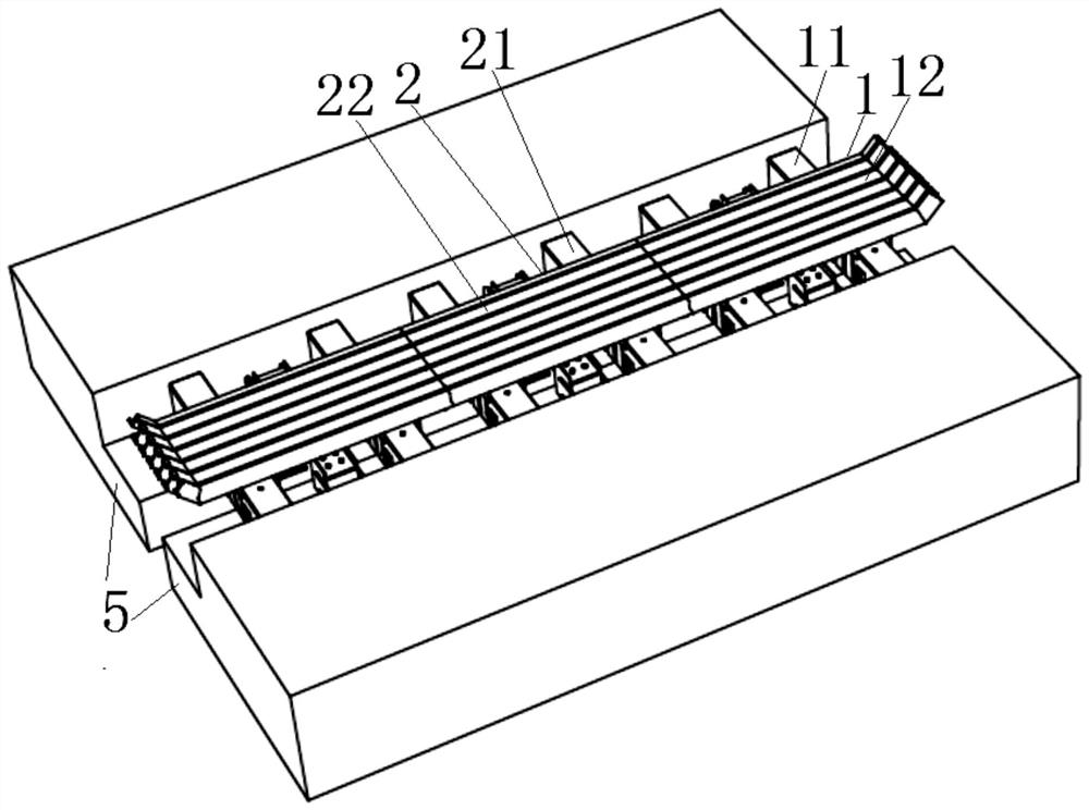
[0032] see figure 1 , figure 2 and image 3 As shown, the present invention has three sections of telescopic units along the transverse length, and the sequential butt joint lengths of these three sections of telescopic units just correspond to the design requirements of the modular telescopic device length at 5 places of the end beam on the bridge. The structure of each segment of the telescopic unit is basically the same as that of the conventional modular telescopic device, the biggest difference being that the transverse length is shorter than that of the integral modular telescopic device. Specifically, taking the telescopic unit-1 as an example, the telescopic unit-1 is mainly composed of two longitudinal joists-11 arranged longitudinally, a support box that is movably assembled at both ends of each longitudinal joist-11, and arranged horizontally. A plurality of beam sections 12 that are movably assembled on each longitudinal joist 11 (wherein the beam sections that ...

Embodiment 2

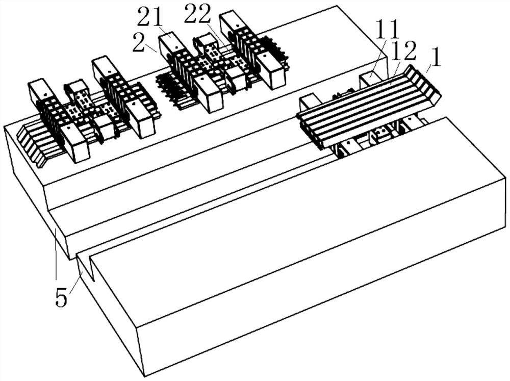
[0046] The present invention has four sections of telescopic units along the transverse length, and the sequential butt joint lengths of these four sections of telescopic units just correspond to the length of the modular telescopic device required by the design at the end beam on the bridge. The structure of each segment of the telescopic unit is basically the same as that of the conventional modular telescopic device, the biggest difference being that the transverse length is shorter than that of the integral modular telescopic device. Specifically, taking the telescopic unit 1 as an example, the telescopic unit 1 mainly consists of a longitudinal joist 1 arranged longitudinally, a support box at both ends of the longitudinal joist movably assembled on the longitudinal joist in a horizontal arrangement A plurality of beam sections on one (among them, the beam sections on both sides and connected with the corresponding supporting box are side beams, and the beam sections betwe...

Embodiment 3

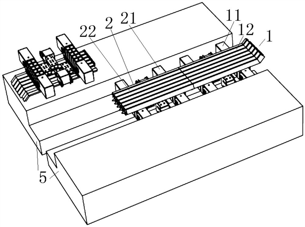
[0059] The other content of this embodiment is the same as that of Embodiment 1, the difference is that there is a positioning pin mechanism between the parts of the two adjacent telescopic units one by one corresponding to the beam section, for example, the one-to-one corresponding beam section with the positioning pin mechanism and the one without The one-to-one corresponding beam sections of the positioning pin mechanism are arranged alternately.


PUM


Abstract

The invention discloses a modularized modulus telescopic device, which has at least two sections of telescopic units along the transverse length, and each section of telescopic units has at least one longitudinal joist and a plurality of beam sections assembled side by side on the longitudinal joist, A locking mechanism is provided between the corresponding beam sections of the two adjacent telescopic units. The locking mechanism is mainly composed of a sliding locking tongue on the first beam section and a fixed locking seat on the second beam section. One is in telescopic unit 1, and the second beam section is in telescopic unit 2. The locking tongue on beam section 1 and the locking seat on beam section 2 are locked together in the form of a "bolt bolt". At least one locking bolt pair is connected between the locking tongue and the locking seat. The invention can effectively and reliably form a high-quality combined whole between two adjacent telescopic units; when a fault occurs, it facilitates high-efficiency and low-difficulty maintenance of the current faulty telescopic unit, and the fault maintenance process is easy and convenient. low cost.

Description

technical field [0001] The invention relates to a modular bridge expansion device, in particular to a modularized modular bridge expansion device. Background technique [0002] Modular bridge expansion device (referred to as "modular expansion device") is an engineering structure arranged at the beam end of the bridge to protect the bridge from thermal expansion and contraction. [0003] The modular telescopic device is mainly composed of multiple supporting joists (that is, longitudinal joists) arranged longitudinally (corresponding to the length direction of the bridge, the same below), supporting boxes that are movably assembled at both ends of each supporting joist, and Horizontal (corresponding to the width direction of the bridge, the same below) arrangement method: multiple middle beams (that is, one type of crossbeams) that are movably assembled on each support joist, and fixedly assembled on each support box on both sides in a horizontal arrangement method It is co...

Claims


Application Information

Patent Timeline
Patent Type & Authority Patents(China)
IPC IPC(8): E01D19/06
CPCE01D19/062
Inventor 石红昌张浩
Owner 成都天元智成科技有限公司
Why Eureka
Try Eureka