Upright post formwork

A column and formwork technology, which is applied in the field preparation of formwork/formwork/work frame, building components, construction, etc., can solve the problems of complex fixing, deformation of the bottom end, high quality of steel formwork, etc., and achieve the purpose of increasing the connection strength Effect

Inactive Publication Date: 2019-09-17
北京碧鑫水务有限公司
View PDF6 Cites 6 Cited by
  • Summary
  • Abstract
  • Description
  • Claims
  • Application Information

AI Technical Summary

Problems solved by technology

[0002] In construction, the existing column construction is generally to build the column formwork first, and then pour the concrete. The column formwork is generally composed of multiple steel formworks to form the shape of the required column. The formwork is fixed together, because the quality of the steel formwork is relatively large, it is more complicated to fix, especially the bolts are difficult to accurately align the bolt mounting holes on the two formwork bodies
[0003] When pouring concrete into the column formwork, the concrete at the bottom of the column flows towards the formwork due to gravity, and as the concrete is continuously poured into the column formwork, the concrete at the bottom end exerts a thrust on the column formwork due to deposition , with the continuous increase of concrete and the continuous increase of thrust, it is easy to deform and damage the adjacent bottom end, resulting in grout leakage

Method used


Image

  • Upright post formwork
  • Upright post formwork
  • Upright post formwork

Examples


Embodiment Construction

[0036] The present invention will be described in further detail below in conjunction with the accompanying drawings.

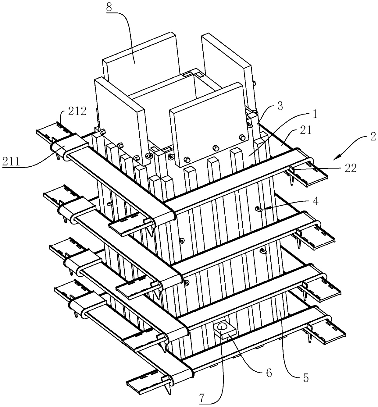
[0037] refer to figure 1 , is a column formwork disclosed in the present invention, comprising four steel formworks 1, and the four steel formworks 1 enclose a rectangular hollow columnar structure. Several fasteners 2 hooped on the four steel templates 1 are arranged outside the four steel templates 1 , and the fasteners 2 are arranged along the height direction of the steel templates 1 . The distance between adjacent fasteners 2 decreases gradually from the top end of the steel formwork 1 to the bottom end of the steel formwork 1 . The left and right sides of the adjacent steel formworks 1 abut against one side close to the inside of the enclosed columnar structure, so that the joints of the adjacent steel formworks 1 are positioned to form an installation notch.

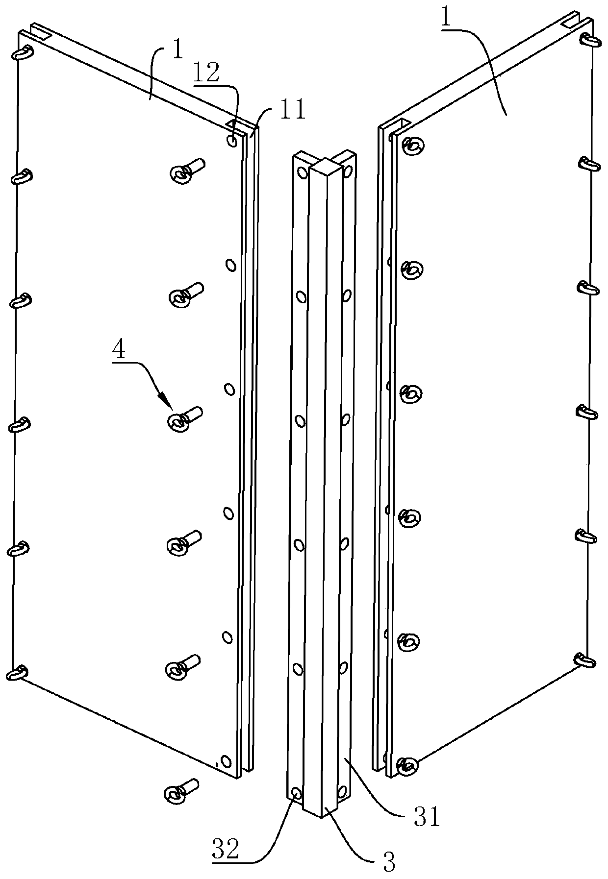
[0038] refer to figure 1 , figure 2 A connecting column 3 with a square cross-section is...


PUM


Abstract

The invention relates to an upright post formwork. The upright post formwork comprises four steel formwork bodies and a plurality of fasteners, wherein the fasteners hoop outside the four steel formwork bodies and are arranged in the height direction of the steel formwork bodies, and the adjacent steel formwork bodies are connected by connecting columns with square cross sections; clamping tables extending vertically and outwardly are correspondingly arranged on the side walls of the two sides, correspondingly opposite to the adjacent steel formwork bodies, of the connecting columns, clamping grooves for the clamping tables to be clamped are formed in the positions, opposite to the clamping tables, of the side walls of the sides, opposite to the connecting columns, of the steel formwork bodies, and the shapes of the clamping grooves are matched with the shapes of the clamping tables; a plurality of perforations are formed in the positions, opposite to the clamping grooves, of the outer side surfaces of the steel formwork bodies in the height direction of the steel formwork bodies, and inserting holes which are formed opposite to the perforations in a one-to-one mode are formed in the clamping tables; and the steel formwork bodies are provided with plug pins with the number being matched with the number of the perforations, and the plug pins penetrate through the perforations and are inserted into the inserting holes. The upright post formwork has the advantages that the sealability of the joints of the adjacent steel formwork bodies is ensured, and thus the occurrence of the situation of mud leakage between the adjacent steel formwork bodies is avoided.

Description

technical field [0001] The invention relates to the technical field of engineering construction, in particular to a column formwork. Background technique [0002] In construction, the existing column construction is generally to build the column formwork first, and then pour the concrete. The column formwork is generally composed of multiple steel formworks to form the shape of the required column. The formwork is fixed together, because the mass of the steel formwork is relatively large, it is more complicated to fix, especially the bolts are difficult to accurately align the bolt mounting holes on the two formwork bodies. [0003] When pouring concrete into the column formwork, the concrete at the bottom of the column flows towards the formwork due to gravity, and as the concrete is continuously poured into the column formwork, the concrete at the bottom end exerts a thrust on the column formwork due to deposition , with the continuous increase of concrete and the continu...

Claims


Application Information

Patent Timeline
Patent Type & Authority Applications(China)
IPC IPC(8): E04G13/02
CPCE04G13/02
Inventor 丁春荣刘天凯闫驰邵国帅
Owner 北京碧鑫水务有限公司
Why Eureka
Try Eureka