

Masonry mortar rapid-laying and anti-falling device
A kind of masonry mortar, fast technology, applied in the direction of construction, building structure, building materials, etc., can solve the problems of poor laying quality, affecting the effect of masonry, low efficiency of mortar laying, etc., to achieve less construction dust and save mortar , The effect of high laying efficiency
- Summary
- Abstract
- Description
- Claims
- Application Information
AI Technical Summary
Problems solved by technology
Method used
Image

Examples
Embodiment 1
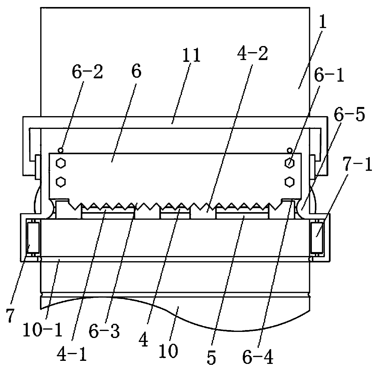
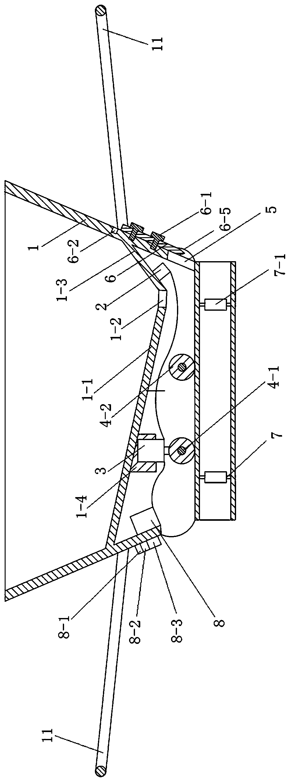
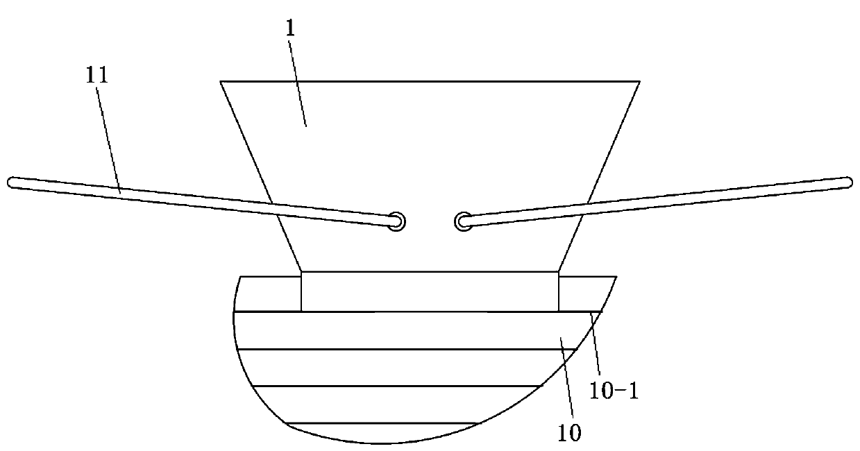
[0020] Embodiment 1, a kind of masonry mortar fast laying anti-falling device, such as figure 1 and figure 2 As shown, it includes a mortar bucket 1 that is movably clamped on both sides of the wall body 10. The bottom wall of the mortar bucket 1 is located between the top and bottom of the mortar bucket 1, and a grout outlet 1-2 is opened on the bottom wall. The mortar hopper 1 is used for storing mortar, and the mortar in the mortar hopper 1 will flow to the top surface of the wall body 10 from the grout outlet 1-2.
[0021] A vibrator 2 and a drive motor 3 are arranged below the bottom wall, and the function of the vibrator 2 is to facilitate discharging the mortar in the mortar hopper 1 from the slurry discharge port 1-2. Two groups of driving wheel sets 4 are installed between the left and right side walls of the mortar bucket 1. The driving motor 3 is connected to the driving wheel set 4 through a reducer. The mortar bucket 1 is provided with a control unit connected t...
Embodiment 2
[0026] Embodiment 2, a fast laying anti-dropping device for masonry mortar, the height between the bottom end of the left and right side walls of the mortar bucket 1 and the lower end surface of the driving wheel group 4 is the thickness of the masonry bricks, ensuring that the present invention is When walking along the body of wall 10, the bottom ends of the left and right side walls correspond to the brick joints of the lower floor. The bottoms of the left and right sides of the mortar bucket 1 are all provided with elastic friction blocks 9 corresponding to the brick joints 10-1, and the elastic friction blocks 9 both do not affect the walking of the present invention, and can repair the lower brick joints.
[0027] Other structures of this embodiment are the same as those of Embodiment 1.
Embodiment 3
[0028] Embodiment 3, a fast laying anti-dropping device for masonry mortar, each set of driving wheel sets 4 includes a wheel shaft 4-1 arranged between the left and right side walls of the mortar bucket 1, and four rollers 4 are arranged on the wheel shaft 4-1 -2, the drive connection of the reducer is in the middle of the axle 4-1. The transmission unit is arranged in the middle of the wheel shaft 4-1, which can ensure the reliability of power transmission and the stability of walking.
[0029] Other structures of this embodiment are the same as Embodiment 1 or 2.
PUM
 Abstract
Description
Claims
Application Information