

Method for detecting water inlet noise of closestool water tank by using A-weighted sound power level measurement method
Patent Information
- Authority / Receiving Office
- CN · China
- Current Assignee / Owner
- 李文杰
- Publication Date
- 2019-09-17
Smart Images
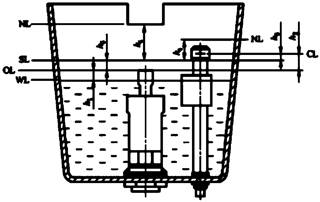
Figure 1 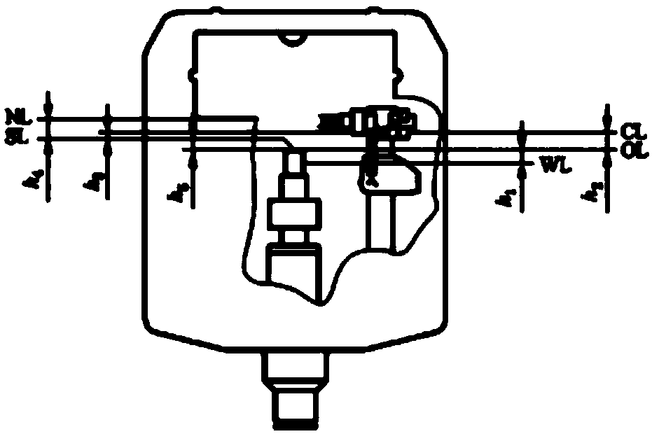
Figure 2 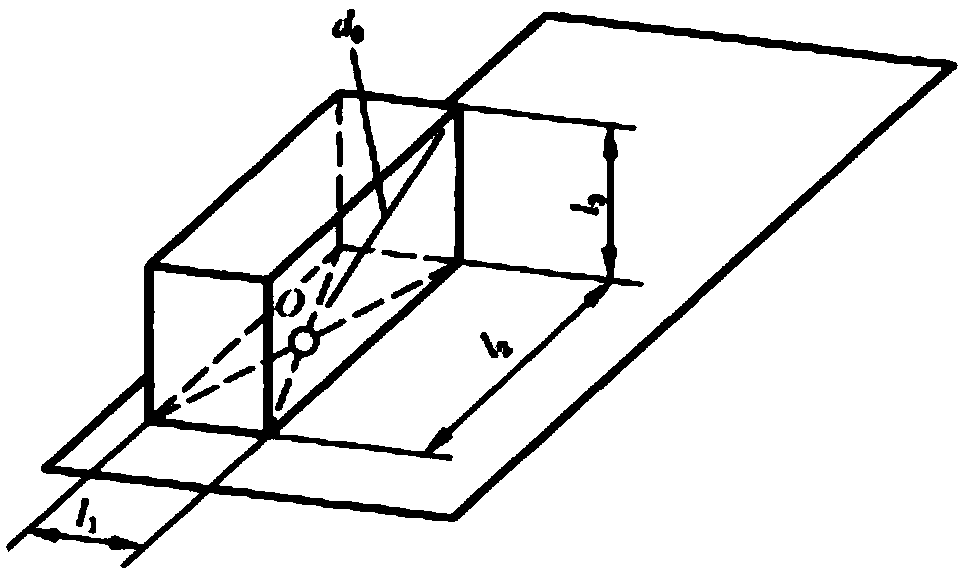
Figure 3
Abstract
Description
technical field
[0001] The present invention relates to a noise quantitative testing method, specifically a slow-time weighting characteristic "S" of a sound level meter A-weighted equivalent sound level to measure the sound power level L by a cumulative percentage on a parallelepiped surface. WA(50) The invention discloses a method for detecting water inlet noise of a water tank inlet valve of a characterized toilet tank, and belongs to the technical field of physical and chemical performance detection of toilet tank accessories. Background technique
[0002] In recent years, as a basic livelihood issue and an important window of civilization, the construction quality of toilets cannot be ignored. With the increasing use of toilets and water tank accessories in key areas of livelihood such as catering, tourism, and home, and the enhancement of people's awareness of health and environmental protection , The noise monitoring and prevention and control of toilet water tank wat...