
Connector and method utilizing connector for charging control

A technology of connectors and connector components, which is applied to the parts of the connection device, the connection/disconnection of the connection device, and the connection, etc., can solve the problems of large power consumption, inability to use external power supply, and limited number of connector slots. for ease of use

Active Publication Date: 2019-09-17
MATRIXED REALITY TECH CO LTD
View PDF6 Cites 5 Cited by
  • Summary
  • Abstract
  • Description
  • Claims
  • Application Information

AI Technical Summary

Problems solved by technology

In this application scenario, data transmission will consume a lot of power
And because the usual number of connector slots of electronic equipment is usually limited (usually one), it is impossible to utilize external power supply to power electronic equipment.

Method used


Image

  • Connector and method utilizing connector for charging control
  • Connector and method utilizing connector for charging control
  • Connector and method utilizing connector for charging control

Examples


Embodiment Construction

[0051] The subject matter described herein will be discussed below with reference to example implementations. It should be understood that the discussion of these implementations is only to enable those skilled in the art to better understand and realize the subject matter described herein, and is not intended to limit the protection scope, applicability or examples set forth in the claims. Changes may be made in the function and arrangement of elements discussed without departing from the scope of the disclosure. Various examples may omit, substitute, or add various procedures or components as needed. Additionally, features described with respect to some examples may also be combined in other examples.

[0052] As used herein, the term "comprising" and its variants represent open terms meaning "including but not limited to". The term "based on" means "based at least in part on". The terms "one embodiment" and "an embodiment" mean "at least one embodiment." The term "anoth...


PUM


Abstract

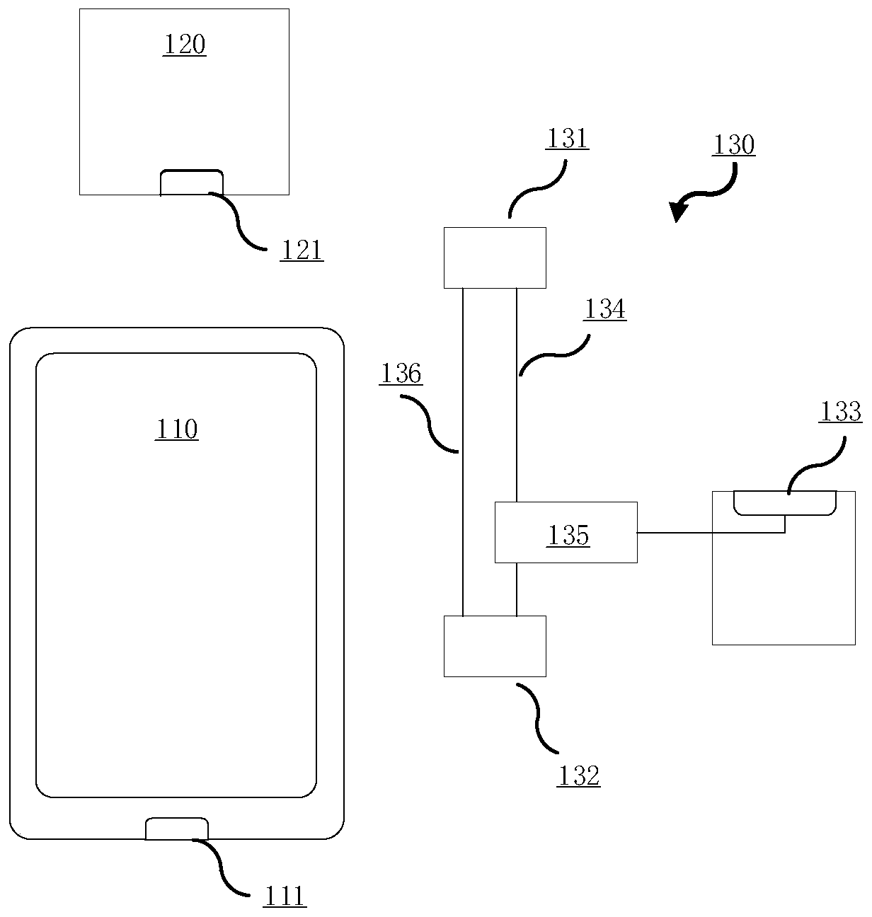
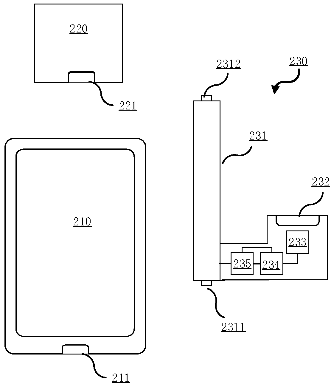
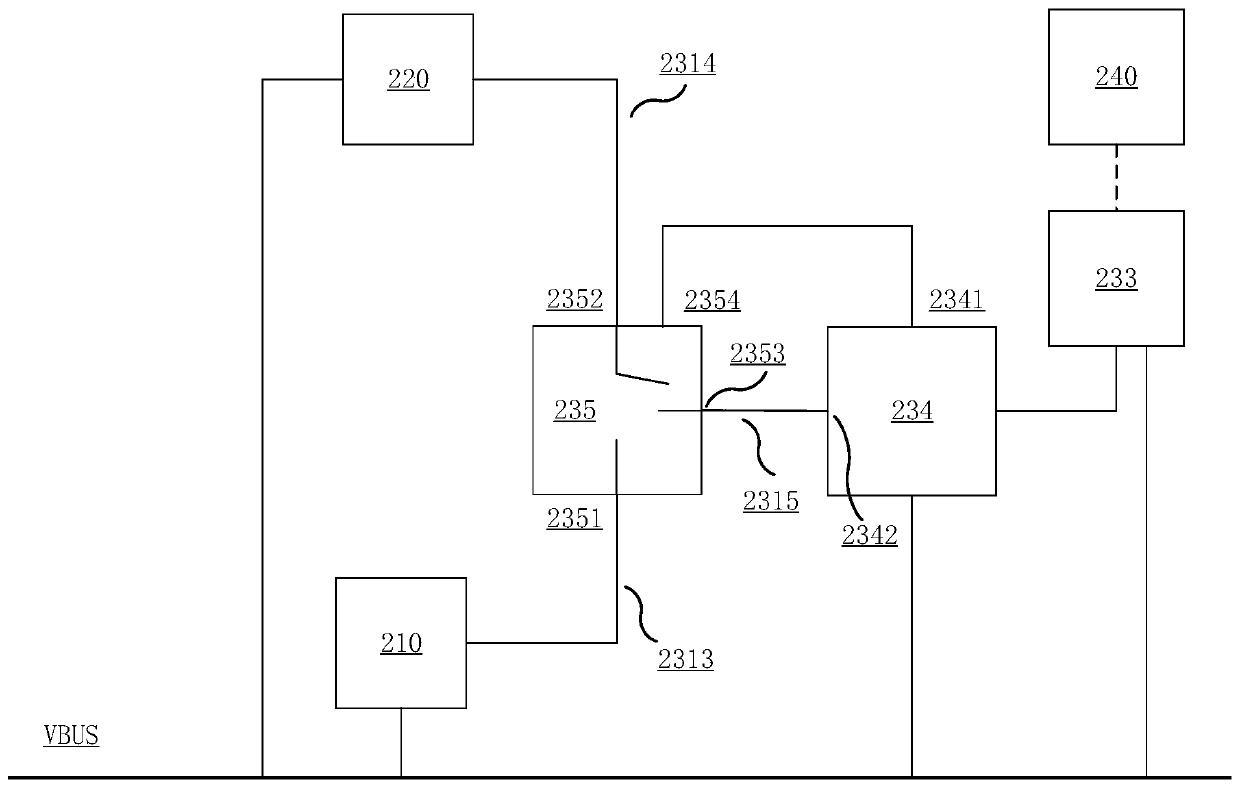
The invention provides a connector coupling a first electronic device and a second electronic device with a power source such that the power source supplies the current to the first electronic device and the second electronic device. The connector includes a first connector assembly, a second connector assembly, a third connector assembly, a power source wire coupled with the first connector assembly, the second connector assembly and the third connector assembly, a first data line, and a signal switching circuit which is configured to detect whether the third connector assembly is coupled with the power source, the first connector assembly is coupled with the second connector assembly when detecting that the third connector assembly is not coupled with the power source, and when detecting that the third connector assembly is coupled with the power source, the first connector assembly is controlled for being coupled with the third connector assembly, a power connection message is transmitted to the first electronic device through the first data line, or the second connector assembly is controlled for being coupled with the third connector assembly, and the power connection message is transmitted to the second electronic device through the first data line.

Description

technical field [0001] The present disclosure relates to the field of electronic communication, in particular, to a connector and a charging control method using the connector. Background technique [0002] Currently, there is an application scenario in which two electronic devices are connected by a connector to transmit data between the two electronic devices. In this application scenario, data transmission consumes a large amount of power. However, since the number of connector slots of an electronic device is usually limited (usually one), it is impossible to use an external power source to power the electronic device. When the electric power of the electronic device is exhausted, it has to stop using and utilize the respective connector slots for charging. Therefore, there is a need in the prior art for a connector that can be powered by an external power source while data is being transmitted between electronic devices. Contents of the invention [0003] In view o...

Claims


Application Information

Patent Timeline
Patent Type & Authority Applications(China)
IPC IPC(8): H01R13/66H01R29/00H01R31/06H01R43/00H01R43/26H02J7/00
CPCH01R29/00H01R31/065H01R13/665H01R43/00H01R43/26H02J7/0042G06F13/4068H02J7/00032H02J7/0036H02J2310/22H01R13/66H01R27/02G06F13/40G06F13/4282G06F2213/0042H01R13/7039H02J7/0045
Inventor 孙鹏达
Owner MATRIXED REALITY TECH CO LTD
Learn More