
Converter circuit fault detection method, readable storage medium and converter

A circuit fault, converter controller technology, applied in circuit devices, emergency protection detection, emergency protection circuit devices, etc., can solve problems such as damage, inability to provide protection, and damage to converter switching devices

Active Publication Date: 2019-09-17
SHENZHEN HOPEWIND ELECTRIC CO LTD
View PDF13 Cites 2 Cited by
  • Summary
  • Abstract
  • Description
  • Claims
  • Application Information

AI Technical Summary

Problems solved by technology

However, because this method is based on the fact that a shoot-through fault has occurred in the bridge arm, and the shoot-through fault is the result of the expansion of the fault after a period of time after the device fails, the existing fault judgment method is often due to untimely judgment and long time ( It usually takes tens of microseconds), leading to the fact that before the protection measures are activated, the converter switching devices may have been damaged or potentially damaged, and cannot provide reliable protection

Method used


Image

  • Converter circuit fault detection method, readable storage medium and converter
  • Converter circuit fault detection method, readable storage medium and converter
  • Converter circuit fault detection method, readable storage medium and converter

Examples


Embodiment Construction

[0072] The present invention will be further described below in conjunction with the accompanying drawings and embodiments.

[0073] The converter circuit fault detection method of the present invention is based on the following converter system implementation, such as Figure 4 As shown, the converter includes a DC filter part U1, a converter bridge part U2, a current detection unit U3, a voltage detection unit U4 and a converter control unit U5. in:

[0074] The DC filtering part U1 is connected in parallel with the converter bridge part U2 and provides stable DC power for the converter bridge part U2, and the converter bridge part U2 converts the DC power into AC power.

[0075] The current detection unit U3 detects the output current of the converter.

[0076] The voltage detection unit U4 detects the voltage difference between the output point of the converter and a certain point of the DC filter part U1 (for example, the positive pole, the negative pole of the DC bus, ...


PUM


Abstract

The invention discloses a converter circuit fault detection method, a readable storage medium and a converter. The method comprises the steps that: the step 1, a converter controller acquires a current direction variable A representing a converter output point, a current actual voltage state variable B representing the converter output point and a current semiconductor switch command C of a converter switching device; the step 2, one of the current direction variable A, the voltage state variable B and the switch command C is selected in the current direction as an object to be compared, the predicted value of the object to be compared is predicted through the other two; and the step 3, the converter controller compares the differences between the predicted value and the actual value of the object to be compared to determine the state of the converter, determines and outputs the fault of the converter when the differences are different, and determines that the converter is normal when the differences are the same. According to the method, only the variable representing the current direction and the variable representing the voltage state are required to be obtained, and the fault determination is performed by combining the switching state of the switching device, so that the calculated amount is less, the error is small, and the determination is rapid, simple and convenient.

Description

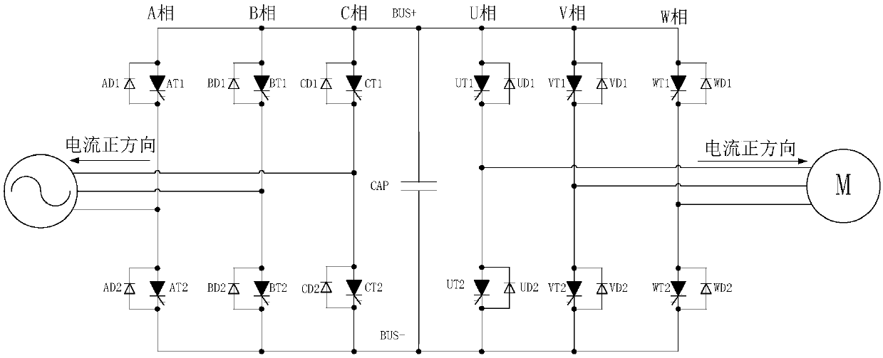
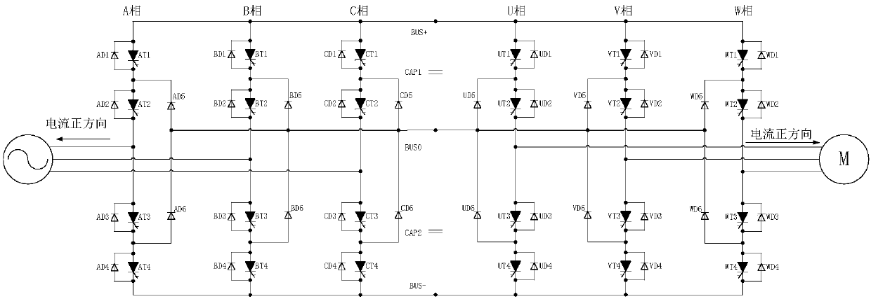
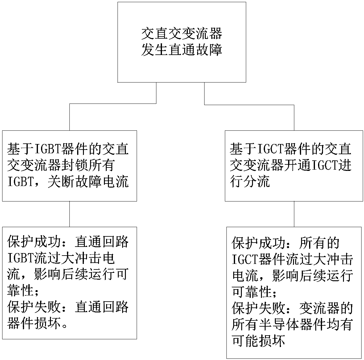
technical field [0001] The invention relates to the technical field of power electronics, in particular to a converter circuit fault detection method, a readable storage medium, and a converter. Background technique [0002] IGBT (Insulated Gate Bipolar Transistor) and IGCT (Integrated Gate Commutated Thyristor) are the two most commonly used fully-controlled devices in the field of AC-DC AC. IGBT is a voltage-controlled device. Extremely increase the control voltage to control the turn-on and turn-off of the device, which can turn off the short-circuit current, and the device has weak overload capacity. IGCT is a current-controlled device. It controls the on and off of the device by injecting current at the gate. Its ability to turn off the current is limited, it cannot turn off the short-circuit current, and the device has a strong overload capability. [0003] Such as figure 1 Shown is a two-level converter composed of fully controlled devices. In the figure, AT1, AT2,...

Claims


Application Information

Patent Timeline
IPC IPC(8): H02H7/12H02H1/00
CPCH02H1/0007H02H1/0092H02H7/1216
Inventor 王武华李海龙郑大鹏周党生
Owner SHENZHEN HOPEWIND ELECTRIC CO LTD
Learn More