
Constant current and constant voltage control circuit based on sampling resistor in chip

A technology of constant current and constant voltage control and sampling resistors, which is applied to battery circuit devices, circuit devices, collectors, etc., can solve the problems of high application cost and output current accuracy, and achieve fewer peripheral components, high stability and precision, and high efficiency effect

Active Publication Date: 2019-09-17
SG MICRO
View PDF7 Cites 3 Cited by
  • Summary
  • Abstract
  • Description
  • Claims
  • Application Information

AI Technical Summary

Problems solved by technology

The disadvantages of the switching power supply charging circuit are as follows: 1. High application cost; 2. From the sampling resistor R sense The voltage drop on the metal connection to the IC can also cause output current accuracy problems

Method used


Image

  • Constant current and constant voltage control circuit based on sampling resistor in chip
  • Constant current and constant voltage control circuit based on sampling resistor in chip
  • Constant current and constant voltage control circuit based on sampling resistor in chip

Examples


Embodiment Construction

[0023] Below with the accompanying drawings ( Figure 1-Figure 2 ) to illustrate the present invention.

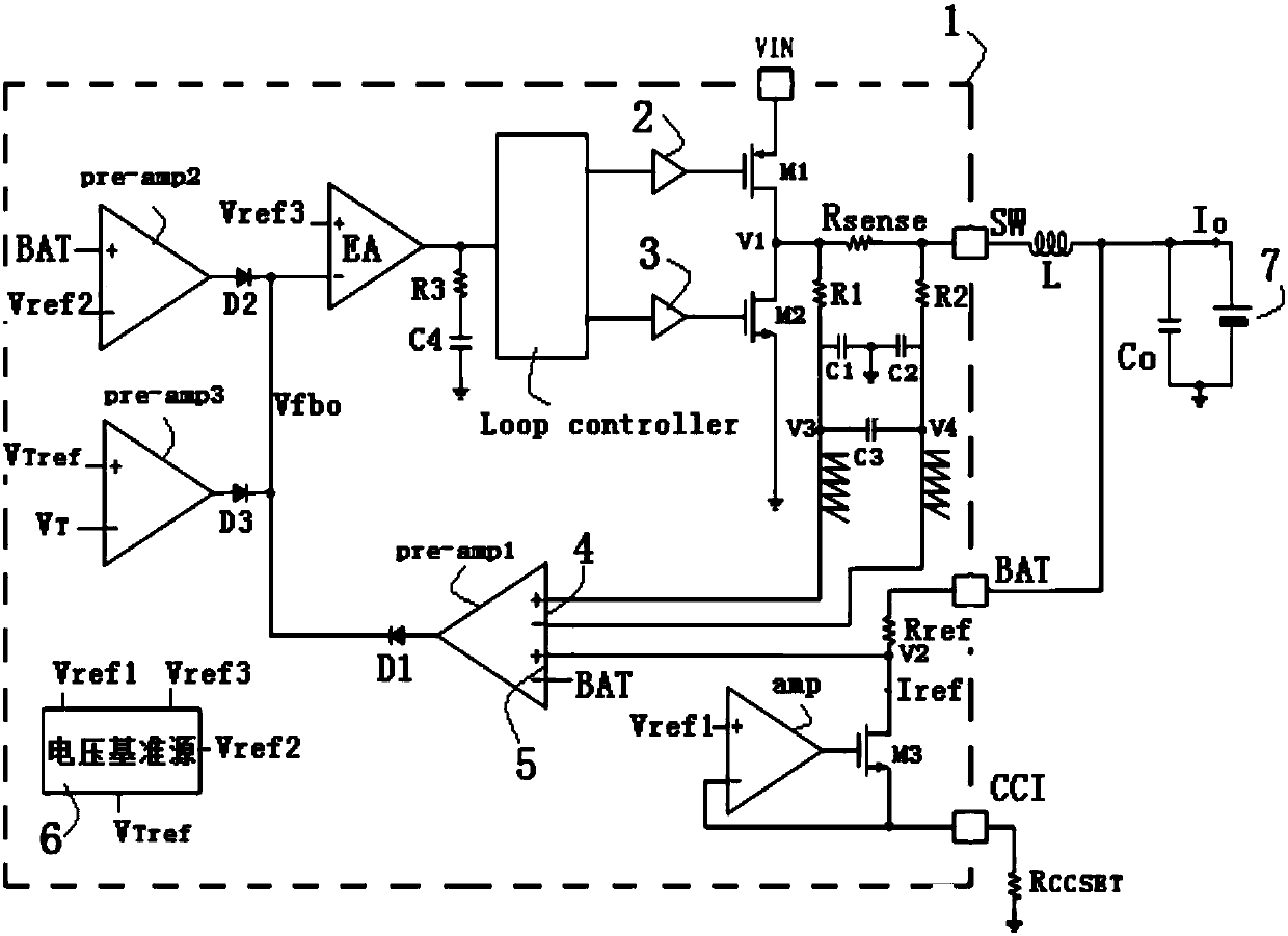
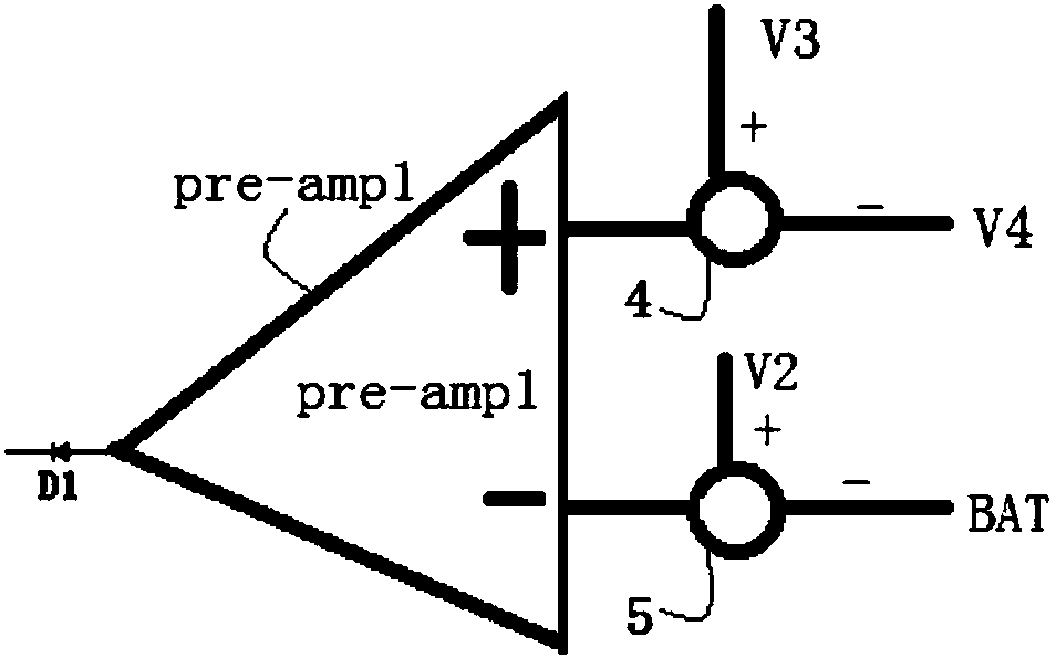
[0024] figure 1 It is a schematic diagram of the structural principle of a constant current and constant voltage control circuit based on the internal sampling resistance of the chip for implementing the present invention. figure 2 yes figure 1 Another connection structure diagram of the first pre-amplifier in . Such as Figure 1 to Figure 2 As shown, a constant current and constant voltage control circuit based on the internal sampling resistance of the chip includes a chip package 1, the chip package 1 has a switch control pin SW, and the outside of the switch control pin SW is connected to an inductor L One end of the inductance L, the other end of the inductance L is the constant current output terminal I 0, and the output voltage node of the dual power transistor is provided with an on-chip sampling resistor Rsense. The internal sampling resistor Rsense of the ...


PUM


Abstract

The invention relates to a constant current and constant voltage control circuit based on a sampling resistor in a chip. By arranging a routing resistor or a Poly resistor which can be formed in the chip as a sampling resistor, peripheral elements of the IC can be reduced, for example, the external sampling resistor of the IC is not needed, the precision of output current can be improved or stabilized, and the cost saving and efficiency improvement are facilitated. The constant current and constant voltage control circuit comprises a chip packaging body which is provided with a switch control pin, the outer side of the switch control pin is connected with one end of an inductor, the other end of the inductor is a constant current output end, and the sampling resistor in the chip is arranged between the other end of the inductor and the output voltage node of a dual-power tube.

Description

technical field [0001] The present invention relates to the constant current control technology of the battery charging application circuit, especially a constant current and constant voltage control circuit based on the internal sampling resistance of the chip. It can reduce the peripheral components of the IC, for example, no external sampling resistor of the IC is needed, and can improve or stabilize the accuracy of the output current, and at the same time, it is also beneficial to save costs and improve efficiency. Background technique [0002] Existing battery charging application circuits have multiple implementation methods for constant current control, which are mainly divided into switch type constant current source and linear constant current source. Linear constant current sources are rarely used in practice due to their low efficiency. Most of the current switching constant current sources use a precision sampling resistor outside the IC to obtain output current...

Claims


Application Information

Patent Timeline
Patent Type & Authority Applications(China)
IPC IPC(8): H02J7/00
CPCH02J7/0077
Inventor 易新敏谢云宁高峡
Owner SG MICRO
Learn More