Remote monitoring system for medical disinfection machine

A technology of a remote monitoring system and a sterilizer, applied in the field of medical devices, can solve the problems of poor sterilization effect, difficult management, inconvenient access, etc., and achieve the effect of good sterilization effect and convenient use.

Inactive Publication Date: 2019-09-20
广州多得医疗设备服务有限公司
View PDF3 Cites 4 Cited by
  • Summary
  • Abstract
  • Description
  • Claims
  • Application Information

AI Technical Summary

Problems solved by technology

[0002] Many small medical equipment need to be sterilized before they can be used again, so the sterilizer has become the standard configuration of various medical institutions. The configuration of a large number of sterilizers has caused certain difficulties to management, and the use of each sterilizer cannot be obtained in time
The existing technology can obtain the relevant data of a single sterili

Method used


Image

  • Remote monitoring system for medical disinfection machine
  • Remote monitoring system for medical disinfection machine
  • Remote monitoring system for medical disinfection machine

Examples


Example Embodiment

[0019] Example 1:

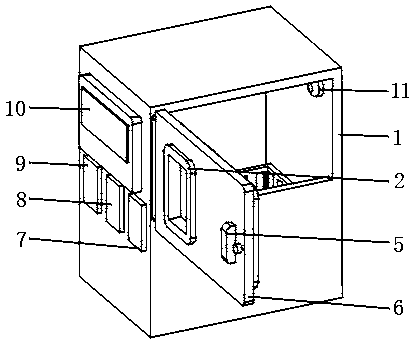
[0020] A remote monitoring system for a medical sterilizer includes a monitoring host and multiple sterilizer main bodies 1. The monitoring host is connected to at least two sterilizer main bodies 1 through a network, and the left side of the sterilizer main body 1 is located near the upper surface. There is a PLC controller 10, which controls the operation of the sterilizer body 1 and sends its working data to the monitoring host. The left side of the sterilizer body 1 is provided with a memory 9 which is used to store the information of the sterilizer body 1. Working data, through the memory 9 and the PLC controller 10 to record the time and status of each disinfection of the disinfection machine. The left side of the disinfection machine body 1 is located near the memory 9 with a GPS locator 8 for use. To locate the position of the sterilizer body 1 and determine that the sterilizer body 1 at that position is running or malfunctioning, a wireless connector ...

Example Embodiment

[0021] Example 2:

[0022] The difference between this embodiment and embodiment 1 is:

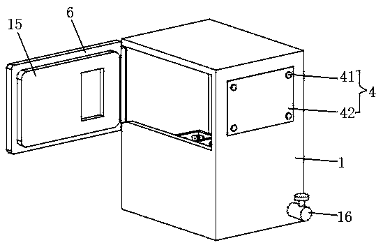
[0023] In this embodiment, a handle 5 and a safety lock are provided on the outer side of the closed door 6 near the edge. The inner side of the closed door 6 is provided with a gasket plate 15 and the outer side of the closed door 6 is provided with a through groove. Install a transparent glass observation window 2.

[0024] Specifically, this arrangement facilitates opening and closing of the door 6, which is more convenient to use, and facilitates observation of the disinfection status of the medical equipment.

Example Embodiment

[0025] Example 3:

[0026] The difference between this embodiment and embodiment 1 is:

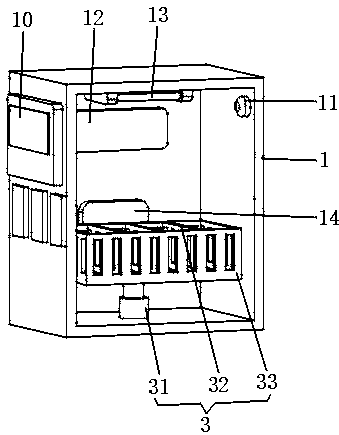
[0027] In this embodiment, the medical equipment placement mechanism 3 includes an electric push rod 31 arranged at the bottom of the disinfection tank. The top of the electric push rod 31 is provided with a placing frame 33, and the bottom of the inner cavity of the placing frame 33 is provided with a partition plate 32. The input end of the rod 31 is electrically connected to the output end of the PLC controller 10. After preliminary cleaning and disinfection, the placing frame 33 is driven up by the electric push rod 31 to remove the medical equipment from the disinfectant, and the drying fan 12 is used for drying. A drying fan 12 is provided on the side of the inner cavity of the main body 1 near the upper surface, and the input end of the drying fan 12 is electrically connected to the output end of the PLC controller 10.

[0028] Specifically, this arrangement is convenient for taking and p...


PUM


Abstract

The invention discloses a remote monitoring system for a medical disinfection machine, which comprises a main body of a disinfection machine, wherein a PLC controller is arranged at a position of a left side of the main body of the disinfection machine near an upper surface. The left side of the main body of the disinfection machine is provided with a memory, and the remote monitoring system of the medical disinfection machine is convenient for supervising the working time and working frequency of the disinfection machine by setting the memory, the PLC controller and an infrared camera, for the operation of the disinfection machine, the monitoring system predicts the fault condition and the replacement of the parts, and takes measures in advance to prevent the equipment from being unable to operate due to malfunctions and the like, the multiple disinfection machines are conveniently supervised by setting a wireless connectors and a GPS positioner, the disinfection can be carried out by setting a disinfection tank, a ultraviolet disinfection lamp, a ultrasonic generator and a drying fan. The disinfection effect is better, and the monitoring system is convenient to place different medical equipment by setting a medical equipment pick-and-place mechanism.

Description

technical field [0001] The invention relates to the technical field of medical equipment, in particular to a remote monitoring system for a medical disinfection machine. Background technique [0002] Many small medical devices need to be sterilized before they can be reused after use, so sterilizers have become the standard configuration of various medical institutions. The configuration of a large number of sterilizers has caused certain difficulties in management, and the usage status of each sterilizer cannot be obtained in time. The existing technology can obtain the relevant data of a single sterilizer, but cannot obtain the usage of a large number of sterilizers, resulting in the inability to carry out network integration for centralized and unified control, and it is impossible to realize remote monitoring to accurately screen out faults or incomplete disinfection. Standard machines are required for timely maintenance, but the disinfection effect is poor and it is inc...

Claims


Application Information

Patent Timeline
IPC IPC(8): A61L2/18A61L2/10A61L2/025A61L2/24
CPCA61L2/025A61L2/10A61L2/18A61L2/24A61L2202/24
Inventor 孟建昇
Owner 广州多得医疗设备服务有限公司
Why Eureka
Try Eureka