Charging and sterilizing base and control circuit

A technology for controlling circuits and charging devices, which is applied to battery circuit devices, disinfection, circuit devices, etc., can solve the problems of being unable to simultaneously charge and sterilize electric toothbrushes, and achieve good disinfection effects and high work efficiency.

Pending Publication Date: 2019-01-15
SHENZHEN XINDIANTONG TECH CO LTD
View PDF0 Cites 2 Cited by
  • Summary
  • Abstract
  • Description
  • Claims
  • Application Information

AI Technical Summary

Problems solved by technology

[0002] The electric toothbrush drives the brush head of the electric toothbrush to vibrate through the vibration of the motor to effectively remove dental plaque. It has the advantages of convenient use and good cleaning effect. However, after the electric toothbrush is used for a period of time, the brush head of t

Method used


Image

  • Charging and sterilizing base and control circuit
  • Charging and sterilizing base and control circuit
  • Charging and sterilizing base and control circuit

Examples


Example

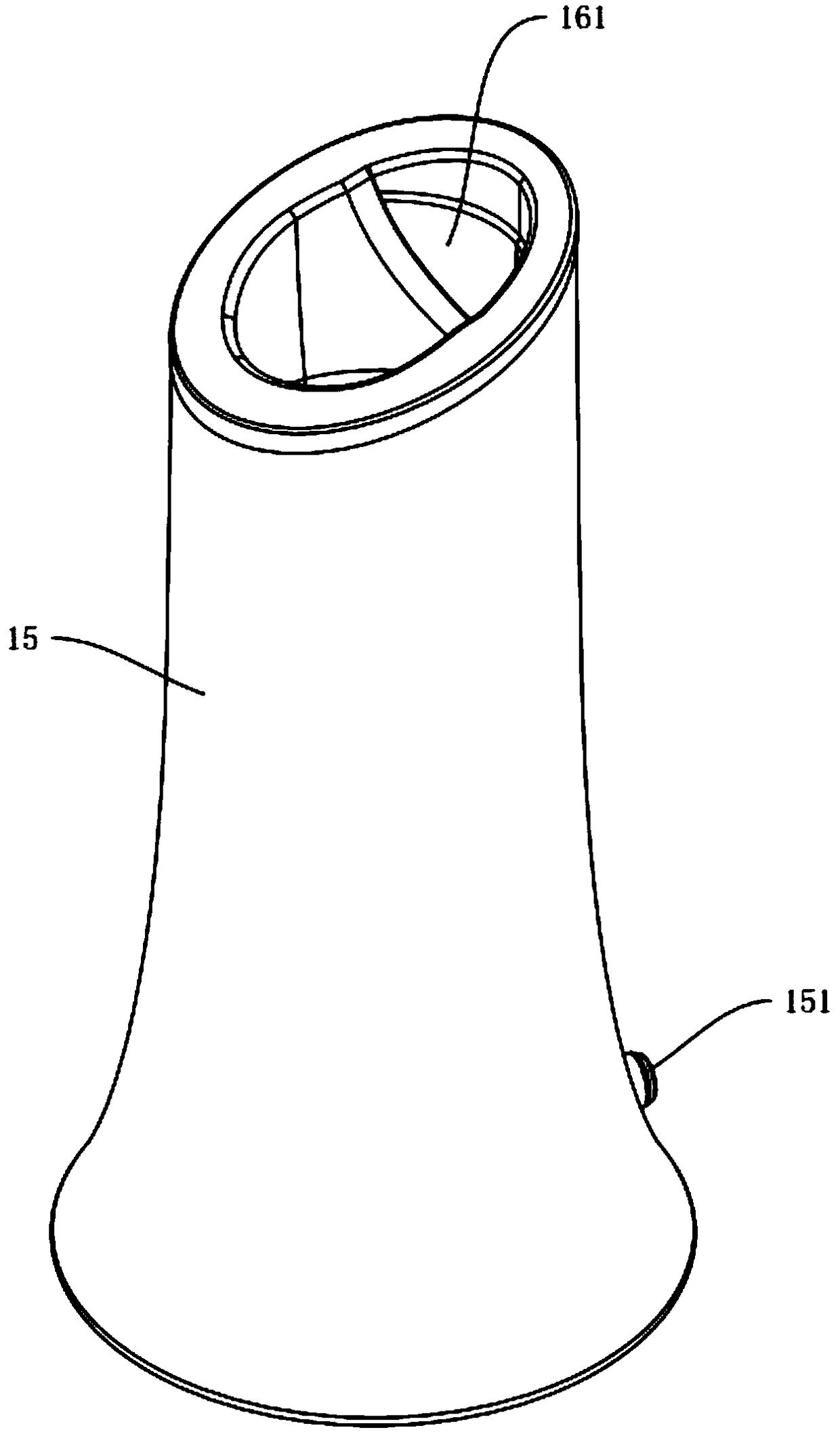
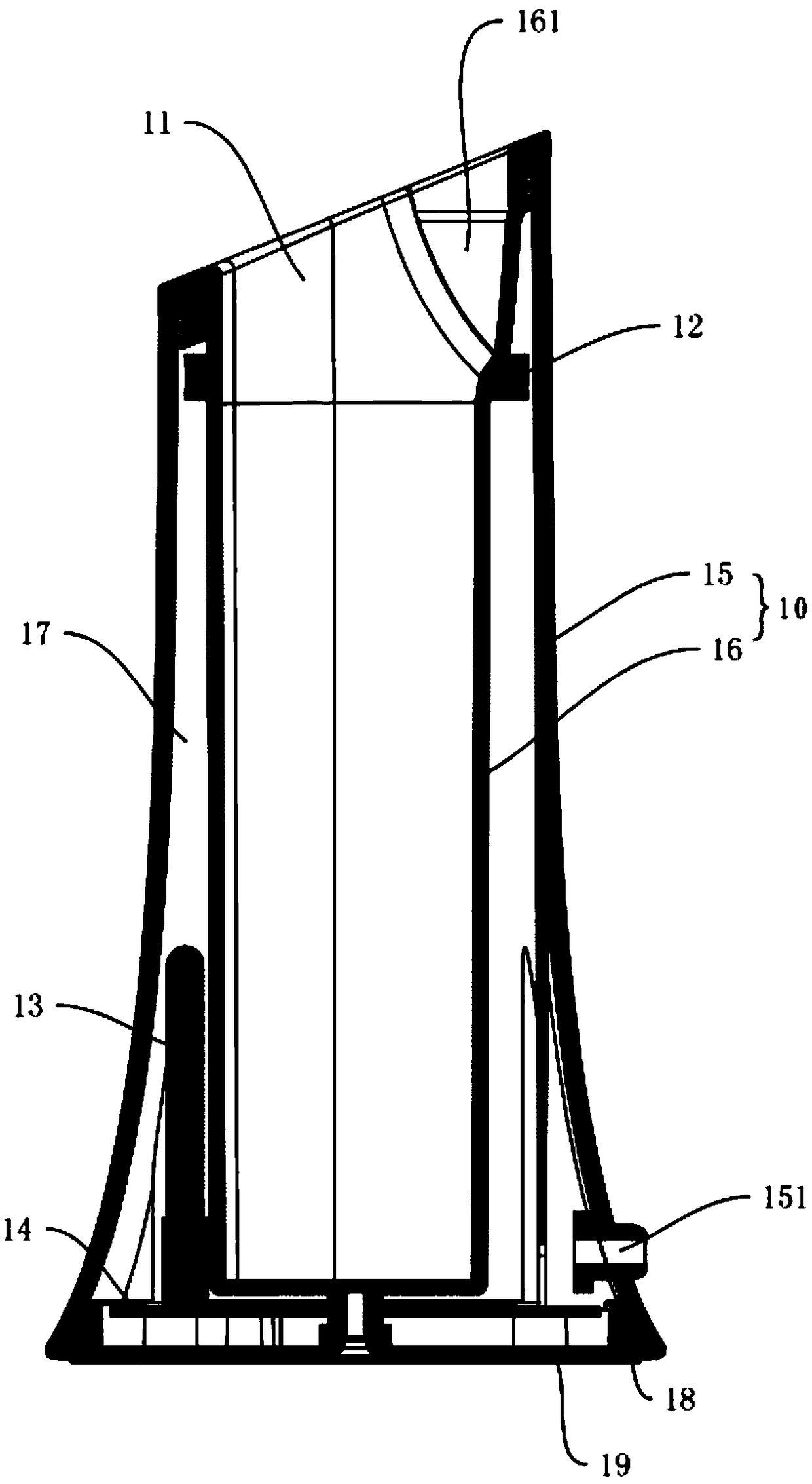
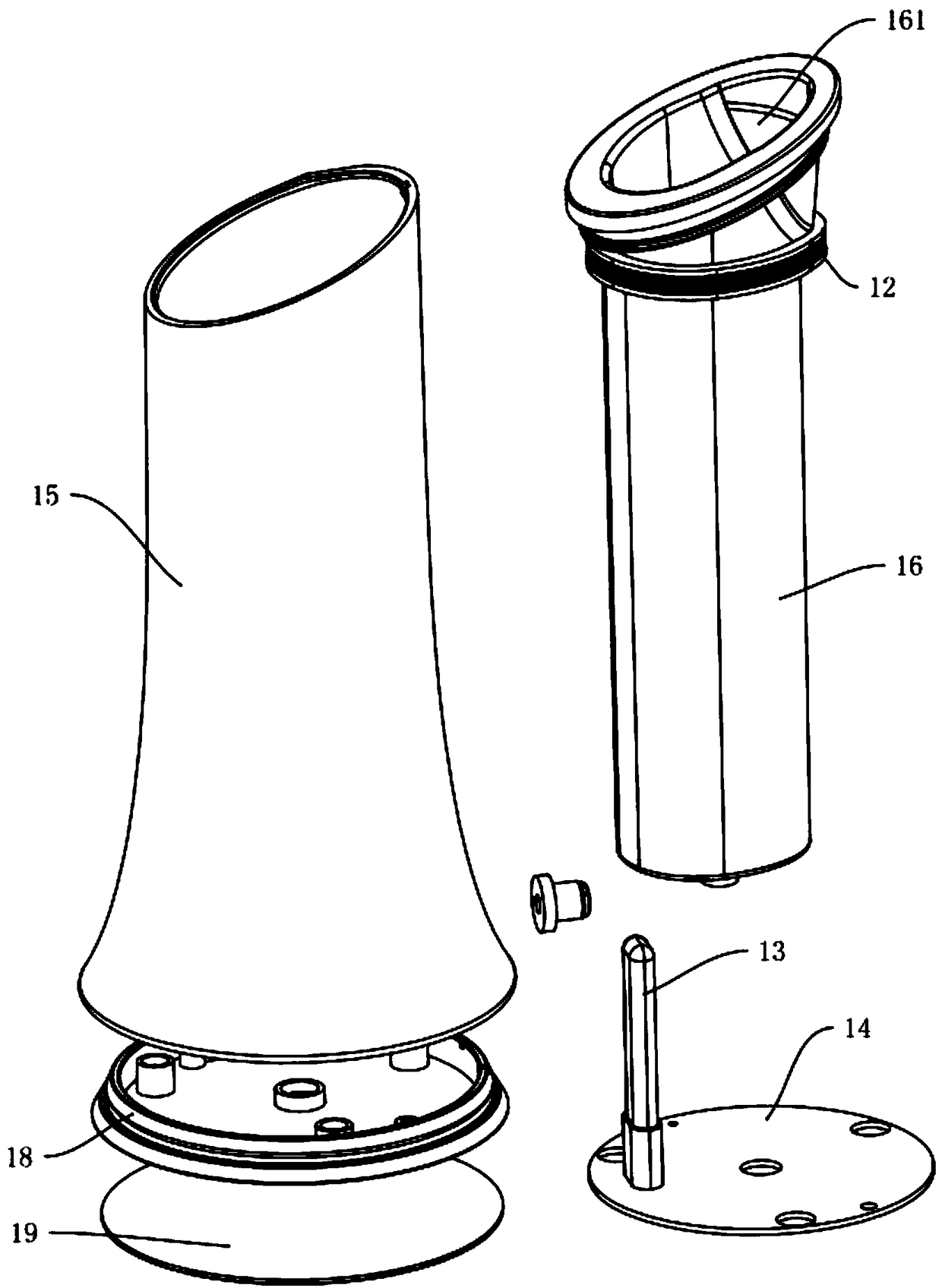
[0032] The first embodiment, such as Figure 1 to Figure 5 As shown, a rechargeable disinfection base includes a housing 10 with a hollow structure. The housing 10 is provided with an insertion port 11 for inserting electrical equipment. The insertion port 11 is arranged on the upper part of the housing 10 . The charging device for charging the electrical equipment 20 is provided with a disinfection device 13 on the inner wall of the housing 10, and a PCB board 14 is provided at the bottom of the housing 10, and the charging device and the disinfection device 13 are electrically connected to the PCB board 14 respectively.

[0033] like Figure 1 to Figure 5 As shown, the charging device is a charging transmitting coil 12, and the electric device 20 may be an electric toothbrush or a facial cleanser. The electric device 20 is provided with a charging receiving coil 21, and the side wall of the casing 10 is provided with a charging interface 151, which is connected to the The P...

Example

[0038] second embodiment

[0039] like Figure 6 to Figure 12 As shown, a control circuit of a charging disinfection base includes a main control unit 30, a disinfection unit 40 and a wireless charging unit 50; the disinfection unit 40 and the wireless charging unit 50 are respectively connected to the main control unit 30, and the wireless charging unit 50 is used to obtain The wireless charging unit 50 transmits the acquired contact signal to the main control unit 30 , and the main control unit 30 activates the disinfection unit 40 to disinfect the electrical equipment 20 after receiving the signal.

[0040] like Figure 6 to Figure 12As shown, the disinfection unit 40 includes a light control module 41 , a light module 42 connected to the light control module 41 , and a buzzer module 43 ; the light control module 41 and the buzzer module 43 are respectively connected to the main control unit 30 . The light module 42 includes a UV lamp,

[0041] like Figure 6 to Figure ...


PUM


Abstract

The invention discloses a charging and sterilizing base and a control circuit. The charging and sterilizing base comprises a shell with a hollow structure, wherein the shell is provided with an insertion port into which the electric equipment is inserted, a charging device for charging the electric equipment is arranged on the inner side wall of the shell, a sterilizing device is arranged on the inner side wall of the shell, a PCB board is arranged on the bottom of the shell, and the charging device and the sterilizing device are electrically connected with the PCB board respectively; Circuitfor control charging and sterilize of a charging and sterilizing base. Its advantage is that the charging and sterilization are carried out simultaneously, and the working efficiency is high. The brush head of the electric equipment is inserted into the housing from the upper opening, and the charging device charges the charging receiving coil of the electric equipment. At that same time, the PCBboard will automatically start the work of the disinfection and sterilization device and can sterilize the brush head of the electric equipment. The PCB board can be sterilize and sterilized by an automatic identification star, a timing manner, a timing ending and an automatic power-off. The whole process is done automatically.

Description

technical field [0001] The invention relates to the technical field of sterilization, in particular to a charging disinfection base and a control circuit. Background technique [0002] The electric toothbrush drives the brush head of the electric toothbrush to vibrate through the vibration of the motor to effectively remove dental plaque. It has the advantages of convenient use and good cleaning effect. However, after the electric toothbrush is used for a period of time, the brush head of the electric toothbrush will breed a lot of bacteria. Also need to charge electric toothbrush regularly simultaneously, existing electric toothbrush sterilizing device can only play the effect of sterilization simply, can't play the effect of charging simultaneously; Electric toothbrushes play a role in sterilization. Contents of the invention [0003] The purpose of the present invention is to solve the deficiencies of the prior art and provide a disinfection charging stand for electric...

Claims


Application Information

Patent Timeline
IPC IPC(8): A61L2/24A61L2/10A61L2/28H02J7/00
CPCA61L2/10A61L2/24A61L2/28H02J7/0044A61L2202/14
Inventor 吴建辉
Owner SHENZHEN XINDIANTONG TECH CO LTD
Why Eureka
Try Eureka