Vacuum paint-dipping device used for transformer production and paint-dipping method thereof

A technology of transformer and vacuum immersion, which is applied in the direction of spraying device, spray booth, etc., can solve the problems of time-consuming, labor-intensive, incomplete, and low degree of automation, and achieve the effect of saving time and effort, easy work of dipping paint, and high degree of automation

Active Publication Date: 2019-09-20
ANHUI HEHAN OPTOELECTRONICS TECH
View PDF7 Cites 3 Cited by
  • Summary
  • Abstract
  • Description
  • Claims
  • Application Information

AI Technical Summary

Problems solved by technology

[0004] The purpose of the present invention is to solve the problem that the existing vacuum paint dipping device has a low degree of automation for the transformer dipping process, and the use of the vacuum paint dipping device is time-consuming and laborious; it is not convenient, fast, Comfortable; the vacuum impregnation device can only spray and impregnate a single transformer at the same time, and the capacity for simultaneously impregnating the transformer is small; before impregnating the transformer, the efficiency of the device to vacuum the inside of the impregnation chamber is slow , not comprehensive, resulting in the impregnation of the paint on the transformer is not fast enough and reliable; the existing vacuum impregnation device is not uniform and comprehensive enough to spray the paint on the transformer, and cannot flexibly and quickly change the effect of the paint spray valve on the device on the transformer. The position and angle of painting lead to low precision and slow efficiency of the vacuum impregnation work of the vacuum impregnation device on transformers; the position of the vacuum impregnation device for impregnation of transformers with different heights is not accurate enough, and a suitable problem is proposed. Vacuum paint dipping device and paint dipping method for transformer production

Method used


Image

  • Vacuum paint-dipping device used for transformer production and paint-dipping method thereof
  • Vacuum paint-dipping device used for transformer production and paint-dipping method thereof
  • Vacuum paint-dipping device used for transformer production and paint-dipping method thereof

Examples


Embodiment Construction

[0045] The technical solutions of the present invention will be clearly and completely described below in conjunction with the embodiments. Apparently, the described embodiments are only some of the embodiments of the present invention, not all of them. Based on the embodiments of the present invention, all other embodiments obtained by persons of ordinary skill in the art without creative efforts fall within the protection scope of the present invention.

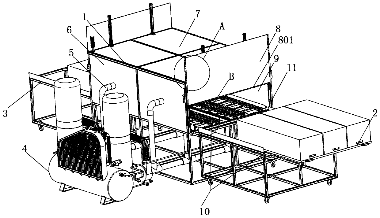
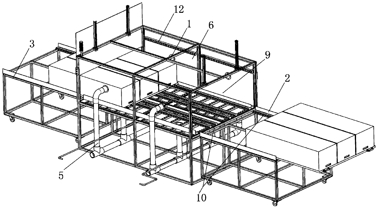
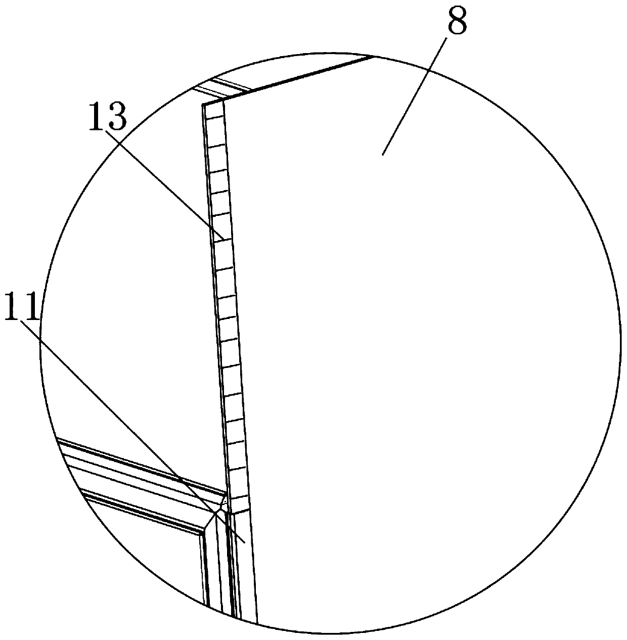
[0046] see Figure 1-11 As shown, a vacuum dipping device for transformer production includes a sealing frame 1, a paint dipping bin 9, a front feeder 2, a rear feeder 3, a vacuum pump 4 and an exhaust pipe 5, and the paint dipping bin 9 is surrounded by a sealed Frame 1, and one side of the sealing frame 1 is provided with a forward delivery platform 2, the other side of the sealing frame 1 is provided with a rear delivery platform 3, and a vacuum pump 4 is provided on one side of the middle part of the sealing frame 1, an...


PUM


Abstract

The invention discloses a vacuum paint-dipping device used for transformer production and a paint-dipping method thereof. The vacuum paint-dipping device comprises a sealing frame, a paint dipping bin, a front conveying table, a rear conveying table, a vacuum pump and a gas exhaust tube, wherein the paint dipping bin surrounds the sealing frame; one side of the sealing frame is equipped with the front conveying table, and the other side of the sealing frame is equipped with the rear conveying table; and one side of the middle part of the sealing frame is equipped with the vacuum pump. According to the vacuum paint-dipping device disclosed by the invention, a transformer is placed on the front conveying table, and a conveying disc drives the transformer to move and convey into the paint dipping bin to subject to paint dipping processing, so that paint dipping work of putting the transformer into the paint dipping bin is easier and is more convenient; a first motor drives an end sealing plate to perform up-down regulating motion through a hobbing gear, so that the end sealing plate can be quickly switched to seal or open and close the paint dipping bin, and therefore, the device is accessed into the transformer more conveniently for performing paint dipping or taking out the paint-dipped transformer, and integral sealing performance for the paint dipping bin by the sealing frame is greatly improved in a mode that a rubber strip is connected to a blocking slot in the lower portion of the end part of the sealing frame.

Description

technical field [0001] The invention relates to a paint dipping device, in particular to a vacuum paint dipping device and a paint dipping method for transformer production, and belongs to the technical field of vacuum paint dipping devices. Background technique [0002] When the transformer is produced, the vacuum impregnation device is indispensable. The main function of the vacuum impregnation is to put the finished winding transformer into the special impregnation chamber, first vacuumize, and then open the paint spray valve to make the transformer under vacuum condition. The paint is dipped below, which can eliminate the air bubbles in the winding and increase the insulation performance of the transformer. [0003] There are still many deficiencies in the existing vacuum dipping device for transformer production. The existing vacuum dipping device has a low degree of automation for the transformer dipping process, and the use of the vacuum dipping device is time-consumi...

Claims


Application Information

Patent Timeline
Patent Type & Authority Applications(China)
IPC IPC(8): B05B16/40B05B16/00B05B13/02B05B15/68B05B12/12
CPCB05B16/95B05B16/40B05B13/0278B05B13/025B05B15/68B05B12/124Y02P70/10
Inventor 夏云
Owner ANHUI HEHAN OPTOELECTRONICS TECH
Why Eureka
Try Eureka