A connection node between a steel beam and a concrete filled steel tube column and its construction method

A technology for steel pipe concrete columns and connecting nodes, which is applied in construction and building structures, can solve the problems of increasing construction volume and cost, affecting concrete pouring in pipes, affecting aesthetics and home layout, etc., and achieves the improvement of construction quality and speed, The effect of reducing formwork time and simple structure

Active Publication Date: 2020-07-03
JILIN UNIV
View PDF9 Cites 0 Cited by
  • Summary
  • Abstract
  • Description
  • Claims
  • Application Information

AI Technical Summary

Problems solved by technology

[0004] There are following deficiencies in the existing connection joints between box steel beams and concrete-filled steel tube columns and their construction methods: (1) due to the need to weld inner partitions in the steel tubes and weld short steel beams outside the columns, the steel beams are then connected to the short steel beams. Using double splint splicing, the construction is complicated, and the welding workload is relatively large
The structure of the partition through joint is simple and convenient for construction, but the rectangular steel pipe needs to be truncated several times in the same layer of columns to weld the partition, which will inevitably increase the construction amount and cost
(3) The outer diaphragm connection, due to its own structural measures, the joint needs a sufficiently large horizontal ring plate to ensure the strength of the joint, and the amount of steel used is relatively large
In addition, the setting of the large-sized outer ring plate makes the indoor corners have convex corners, which affects the appearance and home decoration, brings unnecessary troubles to the architectural design, and has poor adaptability and flexibility.
(4) Due to the need for clapboard welding in the steel pipe, there are certain requirements for the size of the rectangular steel pipe, because when the cross-sectional size is small, it is not only difficult to weld, but also affects the pouring of concrete in the pipe, so it is only suitable for steel pipes with a large cross-sectional size node
In addition, the steel pipes are connected to the inner partitions and beams by welding, and the steel pipes are prone to produce large residual stress and deformation under repeated welding, which leads to delamination or brittle failure of the steel at the joints, which affects the safety of the joints

Method used


Image

  • A connection node between a steel beam and a concrete filled steel tube column and its construction method
  • A connection node between a steel beam and a concrete filled steel tube column and its construction method
  • A connection node between a steel beam and a concrete filled steel tube column and its construction method

Examples


Embodiment 1

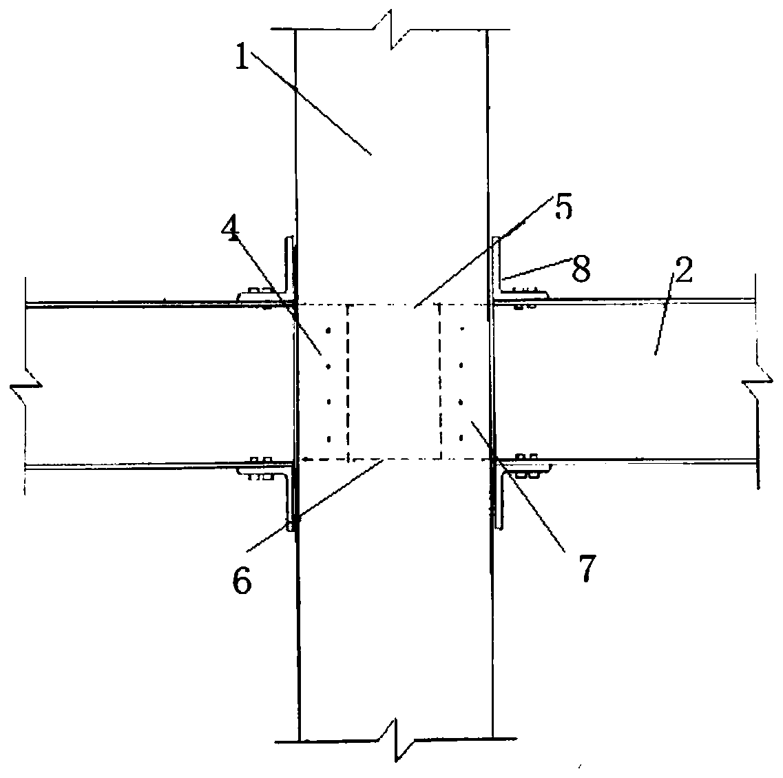
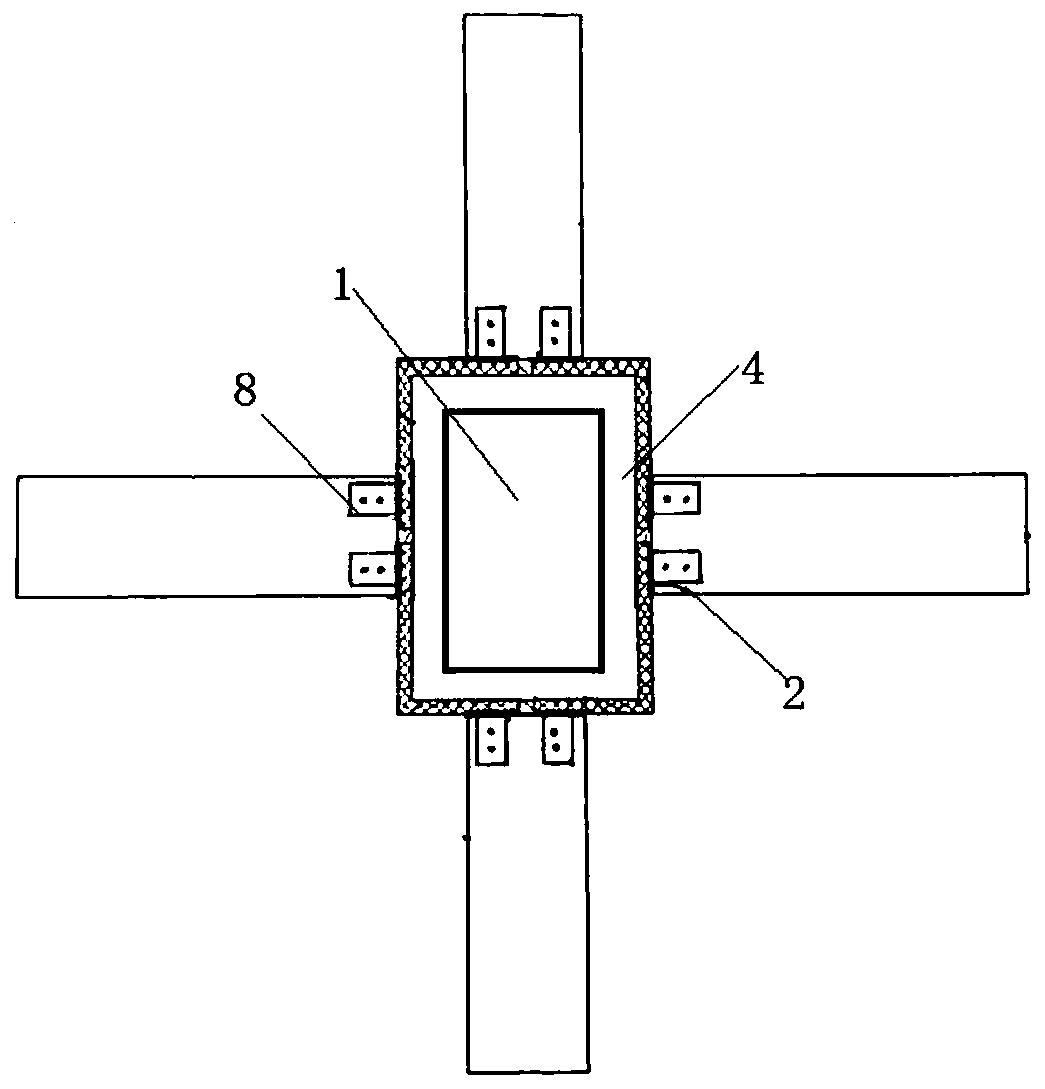
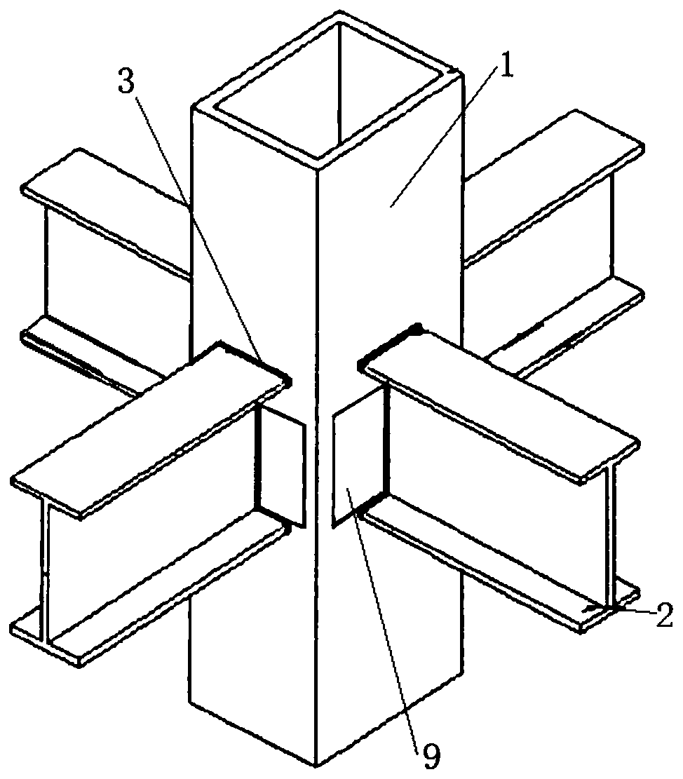
[0031] see Figure 1-3 , a connection node between a steel-filled steel beam and a concrete-filled steel tube column, which is formed by cross-connecting a steel-filled steel tube column 1 with a plurality of steel beams 2, and the side walls of the steel-filled steel tube column 1 are provided with steel beams 2 at uniform intervals in the circumferential direction. The cross-sectional form of the corresponding penetrating structure 3, one end of a plurality of shaped steel beams 2 vertically passes through the corresponding penetrating structure 3 in order to be inserted into the interior of the steel pipe concrete column 1, and the ends of the multiple shaped steel beams 2 are provided with a first node connection hole;

[0032]The connection node includes a reinforcement structure 4, the reinforcement structure 4 is provided with an upper ring flange 5, a lower ring flange 6 and a plurality of reinforcement plates 7, and the reinforcement plate 7 is provided with a second ...

Embodiment 2

[0040] see Figure 1-3 , a connection node between a steel-filled steel beam and a concrete-filled steel tube column, which is formed by cross-connecting a steel-filled steel tube column 1 with a plurality of steel beams 2, and the side walls of the steel-filled steel tube column 1 are provided with steel beams 2 at uniform intervals in the circumferential direction. The cross-sectional form of the corresponding penetrating structure 3, one end of a plurality of shaped steel beams 2 vertically passes through the corresponding penetrating structure 3 in order to be inserted into the interior of the steel pipe concrete column 1, and the ends of the multiple shaped steel beams 2 are provided with a first node connection hole;

[0041] The connection node includes a reinforcement structure 4, the reinforcement structure 4 is provided with an upper ring flange 5, a lower ring flange 6 and a plurality of reinforcement plates 7, and the reinforcement plate 7 is provided with a second...

Embodiment 3

[0077] see Figure 1-3 , a connection node between a steel-filled steel beam and a concrete-filled steel tube column, which is formed by cross-connecting a steel-filled steel tube column 1 with a plurality of steel beams 2, and the side walls of the steel-filled steel tube column 1 are provided with steel beams 2 at uniform intervals in the circumferential direction. The cross-sectional form of the corresponding penetrating structure 3, one end of a plurality of shaped steel beams 2 vertically passes through the corresponding penetrating structure 3 in order to be inserted into the interior of the steel pipe concrete column 1, and the ends of the multiple shaped steel beams 2 are provided with a first node connection hole;

[0078] The connection node includes a reinforcement structure 4, the reinforcement structure 4 is provided with an upper ring flange 5, a lower ring flange 6 and a plurality of reinforcement plates 7, and the reinforcement plate 7 is provided with a second...


PUM


Abstract

The invention provides a connecting joint of profile steel beams and concrete filled steel tube columns and a construction method thereof. The connecting joint is formed by the concrete filled steel tube columns (1) and the profile steel beams (2) through cross-connecting, and through-structures (3) corresponding to profile forms of the profile steel beams (2) are evenly arranged on the side walls of the concrete filled steel tube columns (1) at intervals in the circumferential direction. One ends of the profile steel beams (2) perpendicularly penetrate through the corresponding through-structures (3) to be inserted the concrete-filled steel tube columns (1); the connecting joint comprises a reinforcing structural member (4); the connecting joint comprises a connecting fastener (8) welded to the outer walls of the concrete-filled steel tube columns (1) for connecting and fastening the concrete filled steel tube columns (1) and the profile steel beams (2). The connecting joint of the profile steel beams and the concrete filled steel tube columns belongs to the advanced structural material industry and is simple in structure, clear in transmission path and effective in transmission of bending moments, the purpose of strengthening the joint is achieved, and quick and efficient construction is achieved.

Description

technical field [0001] The invention belongs to the advanced structural material industry, and relates to the technical field of joints of civil engineering structures, in particular to a joint joint between a shaped steel beam and a concrete filled steel pipe column and a construction method thereof. Background technique [0002] Concrete-filled steel tube columns use the synergistic effect of steel tubes and concrete in the process of stress to improve the bearing capacity of the structure. In recent years, with the development of high-rise and super high-rise structures in cities, concrete-filled steel tube columns have gradually been applied to practical In engineering, it has the advantages of light weight, high bending rigidity and good seismic performance. The section of the section steel is an ideal section for beam members mainly resistant to bending and shearing, and has very good axial and torsional resistance. [0003] The connection between the steel beam and t...

Claims


Application Information

Patent Timeline
Patent Type & Authority Patents(China)
IPC IPC(8): E04B1/58
CPCE04B1/185
Inventor 赵大军石欣
Owner JILIN UNIV
Why Eureka
Try Eureka