A full-length anchoring self-drilling anchor rod and anchoring method

A full-length anchoring and self-drilling technology, which is applied in the installation of anchor rods, earthwork drilling, wellbore/well components, etc., can solve the problems of debris easily blocking the anchor rod hole, insufficient support strength, and inconvenient operation for workers , to achieve the effects of mechanized operation, improved operation safety and simple installation process

Active Publication Date: 2021-03-02
陶文斌
View PDF6 Cites 4 Cited by
  • Summary
  • Abstract
  • Description
  • Claims
  • Application Information

AI Technical Summary

Problems solved by technology

[0003] The traditional underground roadway support adopts U-shaped steel, I-beam, bolt end anchor support, etc., which has high labor intensity and poor support effect, and is not suitable for deep mining of coal mines. U-shaped steel and I-beam support have been phased out. The end-anchor support of rods has also gradually revealed its disadvantages, such as a large amount of labor, insufficient support strength, complicated process, and inability to realize mechanized operations, etc.
[0004] The existing anchor bolt technology requires four steps to install the bolt: drilling, loading resin, installing the bolt, rotating the bolt and stirring the resin to anchor the bolt. There are many construction steps, the installation process is slow, and the workers are inconvenient to operate; the labor intensity of the workers is high; The debris generated in the hole is easy to block the anchor hole; the anchoring agent is not stirred evenly, and it is difficult to achieve full-length anchoring; it is not suitable for mechanized operations, etc.

Method used


Image

  • A full-length anchoring self-drilling anchor rod and anchoring method
  • A full-length anchoring self-drilling anchor rod and anchoring method
  • A full-length anchoring self-drilling anchor rod and anchoring method

Examples


Embodiment Construction

[0028] The embodiments of the present invention are described in detail below. This embodiment is implemented on the premise of the technical solution of the present invention, and detailed implementation methods and specific operating procedures are provided, but the protection scope of the present invention is not limited to the following implementation example.

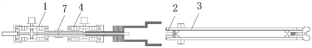
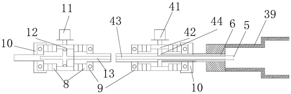
[0029] Such as Figure 1~5 As shown, this embodiment includes a two-way adapter, a water distributor 2 and an anchor body 3; the two-way adapter includes a second adapter 1, a first adapter 4, and the first adapter 4 of this embodiment includes a first quick connector 41 and The first connecting shaft 42, the first connecting shaft 42 is provided with a first through hole 43 and a first ring hole 44 which are not connected to each other along the axial direction, and the first ring hole 44 is coaxially arranged in the first through hole. Outside the hole 43, the first quick connector 41 passes through the first co...


PUM


Abstract

The invention discloses a full-length anchoring self-drilling anchor rod and an anchoring method. A first through hole and a first ring hole which are not connected to each other are arranged in the first connecting shaft along the axial direction, and the first ring hole is coaxial The ring is arranged outside the first through hole, and the first quick connector communicates with the first ring hole after passing through the first connecting shaft; the second connecting shaft is provided with a second through hole in the axial direction, and the second through hole The hole communicates with the second quick joint; the second quick joint, the first through hole and the second through hole are connected to form an intermediate outlet passage for communicating with high-pressure water, and the first quick joint and the first annular hole are used to communicate with low pressure water. A peripheral outlet passage for water; the outer passage communicates with the gap between the steel pipe and the rod body, the central passage communicates with the end of the steel pipe, and the drill bit is connected to the head end of the steel pipe. The overall installation process of the present invention is simple, and the bolt can be successfully installed through the bolter, which improves the operating safety of workers, reduces labor risks, and realizes mechanized operations at the same time.

Description

technical field [0001] The invention relates to a bolt support technology, in particular to a full-length anchor self-drilling bolt and an anchoring method. Background technique [0002] Coal, as one of the important energy sources in our country, will last for a long time. Coal mine production must be safe and efficient. It is getting more and more serious, and it has a great influence on the section of the underground roadway, causing serious safety hazards to mine ventilation, transportation, pedestrians, etc., and the disrepair of the underground roadway must be controlled. [0003] The traditional underground roadway support adopts U-shaped steel, I-beam, bolt end anchor support, etc., which has high labor intensity and poor support effect, and is not suitable for deep mining of coal mines. U-shaped steel and I-beam support have been phased out. The end-anchor support of the rod also gradually reveals its disadvantages, such as a large amount of labor, insufficient sup...

Claims


Application Information

Patent Timeline
Patent Type & Authority Patents(China)
IPC IPC(8): E21D20/00E21D20/02E21D21/00
CPCE21B21/00E21D20/003E21D20/025E21D21/00
Inventor 陶文斌
Owner 陶文斌
Why Eureka
Try Eureka