
Total reflection gas-liquid interface flow display method and gas-liquid interface position identification method

A gas-liquid interface, flow display technology, applied in liquid level indicators, lubrication indicating devices, liquid/fluid solid measurement and other directions, can solve the problems of multiple invalid information, poor image contrast, inability to accurately identify the position of the gas-liquid interface, etc. To achieve the effect of reducing invalid information and enhancing strength

Active Publication Date: 2020-11-03
PEKING UNIV
View PDF16 Cites 0 Cited by
  • Summary
  • Abstract
  • Description
  • Claims
  • Application Information

AI Technical Summary

Problems solved by technology

[0004] The invention provides a total reflection gas-liquid interface flow display method and a gas-liquid interface position recognition method to solve the problem that the contrast of the image obtained by the flow display method used in the existing gas-liquid interface recognition process is poor and contains relatively large A lot of invalid information leads to the technical problem of being unable to accurately identify the position of the gas-liquid interface

Method used


Image

  • Total reflection gas-liquid interface flow display method and gas-liquid interface position identification method
  • Total reflection gas-liquid interface flow display method and gas-liquid interface position identification method
  • Total reflection gas-liquid interface flow display method and gas-liquid interface position identification method

Examples


Embodiment Construction

[0070] The embodiments of the present invention will be described in detail below with reference to the accompanying drawings, but the present invention can be implemented in various ways defined and covered below.

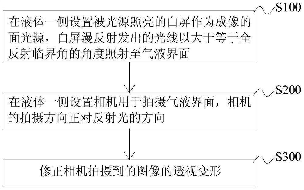
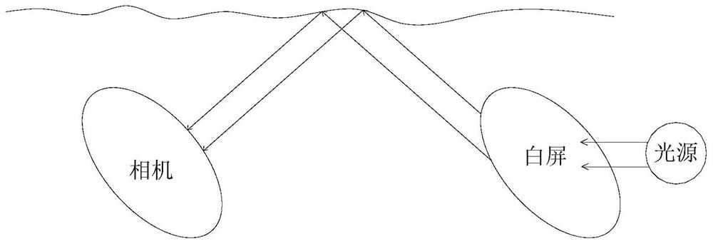
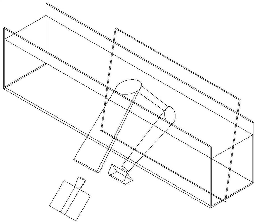
[0071] Such as figure 1 , figure 2 and image 3 As shown, the first embodiment of the present invention provides a total reflection type gas-liquid interface flow display method, which can provide a high-contrast image in the process of identifying the position of the gas-liquid interface, and the obtained image almost only includes the liquid side The image formed by reflection, excluding the image formed by refracted light on the gas side, contains very little invalid information in the image, so that the position of the gas-liquid interface can be quickly and accurately identified from the high-contrast image. The total reflection gas-liquid interface flow display method includes the following steps:

[0072] Step S100: setting a white screen illuminated by...


PUM

PropertyMeasurementUnit
diameteraaaaaaaaaa
diameteraaaaaaaaaa

Abstract

The invention discloses a total reflection type gas-liquid interface flow display method and a gas-liquid interface position recognition method. In the total reflection gas-liquid interface flow display method of the present invention, a white screen illuminated by a light source is arranged on the side of the liquid as a surface light source for imaging, and the light emitted by the diffuse reflection of the white screen is irradiated to the surface at an angle greater than or equal to the critical angle of total reflection. At the gas-liquid interface, the incident light will be totally reflected on the gas-liquid interface, and the light will not pass through the gas-liquid interface and be refracted to the gas side, which greatly enhances the intensity of the reflected light. On the other hand, the light on the gas side It cannot be refracted into the side of the liquid and propagates along the direction of the aforementioned reflected light, reducing invalid information. Then make the shooting direction of the camera face the direction of the reflected light, so as to capture a high-contrast gas-liquid interface image, which basically does not contain invalid information, so that the gas can be quickly and accurately identified on the basis of the obtained high-contrast image. The position of the liquid interface. Moreover, the method for displaying the total reflection air-liquid interface flow of the present invention can still obtain detailed information of all interface positions when there is splashing or spraying.

Description

technical field [0001] The present invention relates to the field of fluid mechanics experiments, in particular to a total reflection gas-liquid interface flow display method, and also to a gas-liquid interface position recognition method using the above-mentioned total reflection gas-liquid interface flow display method. Background technique [0002] Particle image velocimetry (PIV) is a measurement method often used in fluid mechanics experiments. It can measure the instantaneous velocity field of a fluid in a certain area. Take two photos in a short time, and the velocity of the fluid microgroups in the shooting area can be calculated from the position changes of the tracer particles on the photos in the two moments (this velocity is the velocity on the plane, that is, there are two components) . The most important calculation method is to divide the picture into several small blocks (query windows), and calculate the correlation coefficient of the photo brightness betwe...

Claims


Application Information

Patent Timeline
Patent Type & Authority Patents(China)
IPC IPC(8): G01F23/00G01F23/22G01P5/22G01N15/00
CPCG01F23/22G01P5/22G01N15/00G01N2015/0003G01N2015/0046G01N2015/0053G01F23/80
Inventor 李存标陈钧伟
Owner PEKING UNIV
Learn More