Spatial position tracking method and system for target

A space position and tracking system technology, applied in the field of target space position tracking method and system, can solve the problem of conflict between area and resolution

Pending Publication Date: 2019-09-20
SHENZHEN UNIV
View PDF4 Cites 1 Cited by
  • Summary
  • Abstract
  • Description
  • Claims
  • Application Information

AI Technical Summary

Problems solved by technology

At present, the detection depth of the planar capacitive sensor can be improved by increasing the area of ​​the electr...

Method used


Image

  • Spatial position tracking method and system for target
  • Spatial position tracking method and system for target
  • Spatial position tracking method and system for target

Examples


no. 1 example

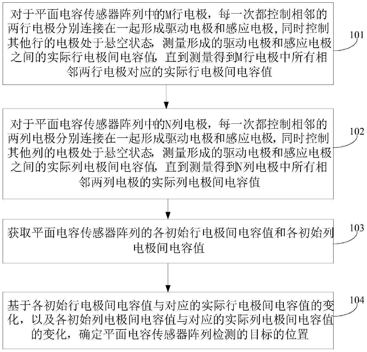
[0024] An embodiment of the present application provides a method for tracking a spatial position of a target, and the method is applied to a planar capacitive sensor array, and the planar capacitive sensor array includes M*N electrodes.

[0025] see figure 1 , the spatial position tracking method of the target includes:

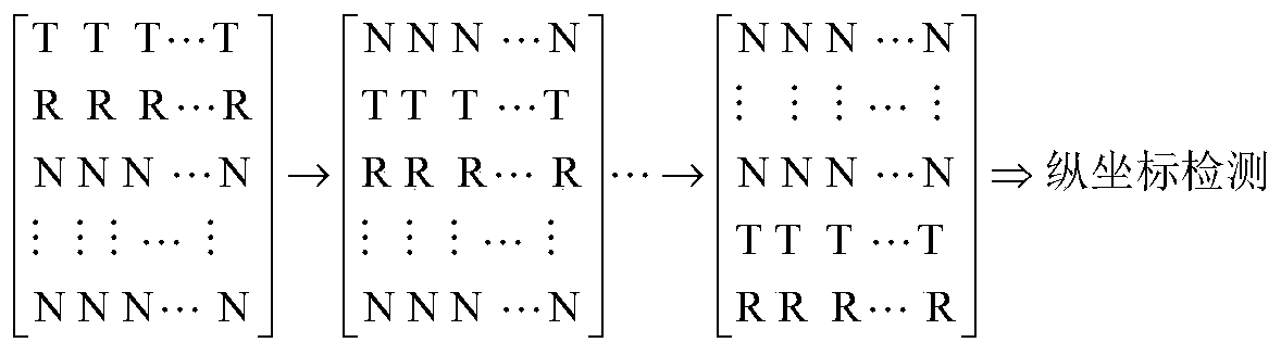
[0026] Step 101, for M rows of electrodes in the planar capacitive sensor array, each time control two adjacent rows of electrodes to be connected together to form driving electrodes and sensing electrodes, and simultaneously control the electrodes of other rows to be in a floating state, and measure the formed driving electrodes and the actual row-electrode capacitance value between the sensing electrodes, until the actual row-electrode capacitance value corresponding to all the adjacent two row electrodes in the M row electrodes is measured, wherein, for all the adjacent two-row electrodes, the upper A row of electrodes is connected together to form the s...

no. 2 example

[0066] see Image 6 , the present embodiment proposes a spatial position tracking system of a target, the system comprising: a planar capacitive sensor array and a control device connected to the planar capacitive sensor array, the planar capacitive sensor array includes M*N electrodes, and the control device includes:

[0067] The row electrode control module 601 is used to control the electrodes of the M rows in the planar capacitive sensor array to connect two adjacent rows of electrodes to form the driving electrodes and the sensing electrodes, and to control the electrodes of other rows to be in a suspended state, Measure the actual row-electrode capacitance between the formed driving electrodes and the sensing electrodes until the actual row-electrode capacitance corresponding to all two adjacent row electrodes in the M row electrodes is measured, wherein, for all the adjacent two-row electrodes , the upper row of electrodes are connected together to form the same type o...


PUM


Abstract

The invention discloses a spatial position tracking method and system for a target. For M rows (N columns) of electrodes in the planar capacitive sensor array, two adjacent rows (columns) of electrodes are respectively controlled to be connected together to form a driving electrode and an induction electrode; meanwhile, electrodes in other rows (columns) are controlled to be in a suspended state; measuring an actual inter-row (column) electrode capacitance value between the formed driving electrode and the formed sensing electrode is measured until actual inter-row (column) electrode capacitance values corresponding to all two adjacent rows (columns) of electrodes in the M rows (N columns) of electrodes are obtained through measurement, and obtaining the inter-electrode capacitance value of each initial row and the inter-electrode capacitance value of each initial column of the planar capacitive sensor array are obtained; and determining the position of the target is determined based on the change of the capacitance values between the row and column electrodes. The electrodes in each row and each column are connected to increase the area of the electrodes, so that the area of the sensor formed by the electrodes is increased, and the detection distance of the sensor is increased; meanwhile, traditional sensor measurement times are reduced, and system measurement time is shortened.

Description

technical field [0001] The present application relates to the field of sensor detection, in particular to a method and system for tracking a spatial position of a target. Background technique [0002] In recent years, human-computer interaction technology has been successfully applied in many fields such as entertainment, medical care, smart home, automobile, education, etc., and has gradually integrated into everyone's life. Planar capacitive sensors are widely used in ECT imaging, humidity detection, distance measurement, human body detection and human-computer interaction technology due to their advantages of low price and simple manufacture. [0003] However, most of the current human-computer interactions of planar capacitive sensors are applied to short-distance (for example, less than 20cm) interactions, which greatly limits the application of planar capacitive sensors in human-computer interaction. At present, the detection depth of the planar capacitive sensor can ...

Claims


Application Information

Patent Timeline
IPC IPC(8): G06F3/044G06F3/041
CPCG06F3/044G06F3/0416
Inventor 何春龙叶勇赵晓霞裴向东郭卫卫
Owner SHENZHEN UNIV
Why Eureka
Try Eureka