
Modeling method for multi-point grounding fault of wound iron core under inter-chip short circuit

A multi-point grounding and modeling method technology, which is applied in the direction of instruments, calculations, electrical digital data processing, etc., can solve the problems of inaccurate judgment and analysis of fault current, increased core loss, and short circuit between chips.

Active Publication Date: 2019-09-20
SOUTHWEST JIAOTONG UNIV +2
View PDF7 Cites 2 Cited by
  • Summary
  • Abstract
  • Description
  • Claims
  • Application Information

AI Technical Summary

Problems solved by technology

The multi-point grounding of the wound core is one of the most typical and most harmful faults of the iron core. A fault current will appear in the cross section of the wound core. The continuous fault current will increase the loss of the wound core and generate a large amount of heat, resulting in the insulation between the silicon steel sheets of the core. Damage or even inter-chip short circuit, which will cause an increase in the eddy current loss of the wound core, and its safety hazards cannot be underestimated
[0003] At present, real-time monitoring of the current of the core ground wire is usually used, and the threshold value is set by empirical formula to judge whether a multi-point ground fault occurs. The magnitude of the ground current of transformers with different structures is also different. When a short circuit occurs between chips, the fault current is even higher. large, so it is impossible to accurately judge and analyze the fault current

Method used


Image

  • Modeling method for multi-point grounding fault of wound iron core under inter-chip short circuit
  • Modeling method for multi-point grounding fault of wound iron core under inter-chip short circuit
  • Modeling method for multi-point grounding fault of wound iron core under inter-chip short circuit

Examples


Embodiment Construction

[0044] The implementation process of the present invention will be further described in detail below in conjunction with the accompanying drawings.

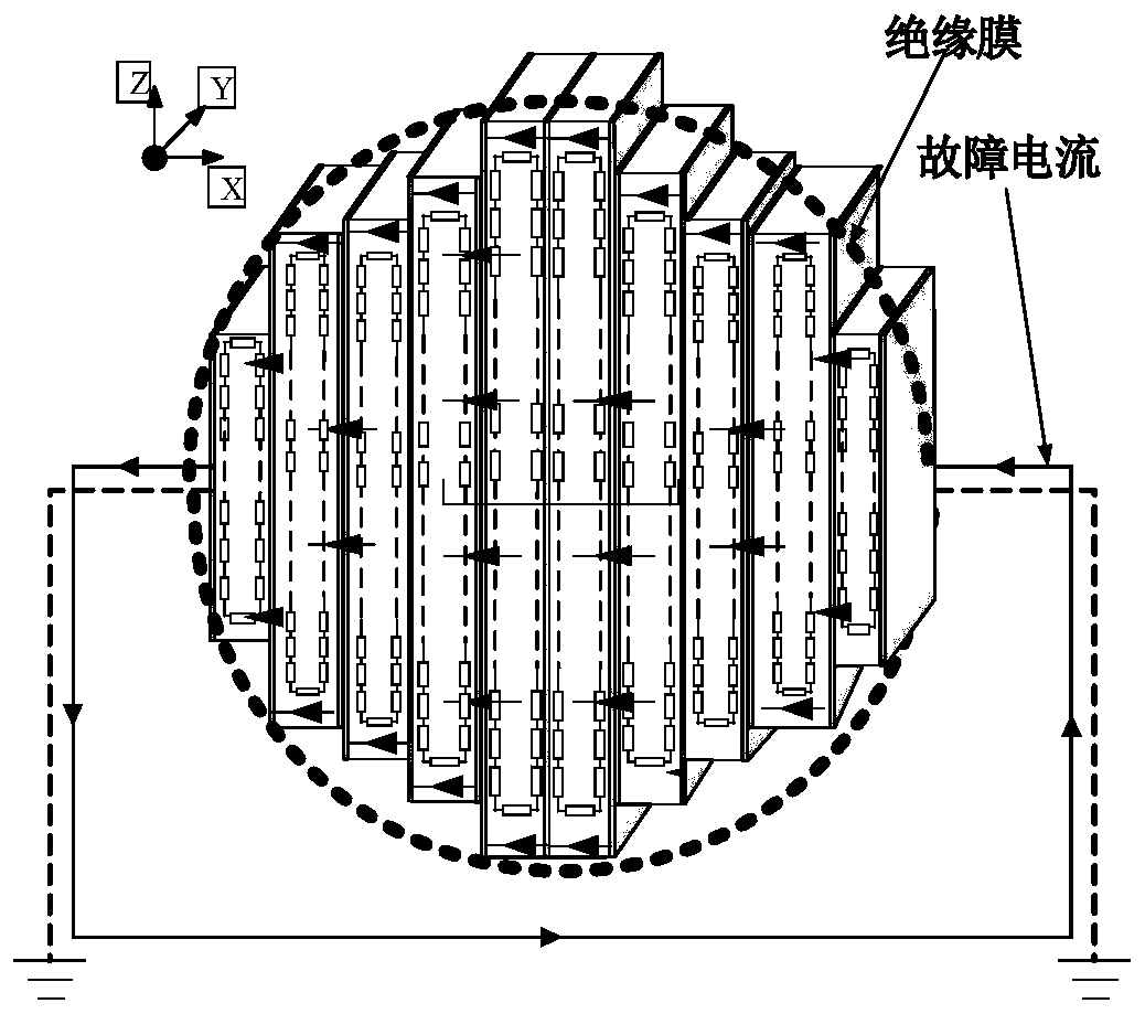
[0045] figure 1 It is a schematic diagram of the multi-point grounding fault current flowing in different directions of the cross section of the wound iron core of the present invention. When a multi-point grounding short circuit fault occurs in the iron core, the iron core forms a loop through the earth, and a current will be generated on this loop in the alternating electromagnetic field, and its flow direction is as follows: figure 1 Shown are primarily along the x and z directions. Due to the influence of the skin effect, the current will only flow on both sides of the silicon steel sheets. The equivalent resistance parameters between each level of silicon steel sheets are derived. The current flow area should be obtained from the skin depth δ, and the resistance calculation formula must also consider each level. Winding ...


PUM


Abstract

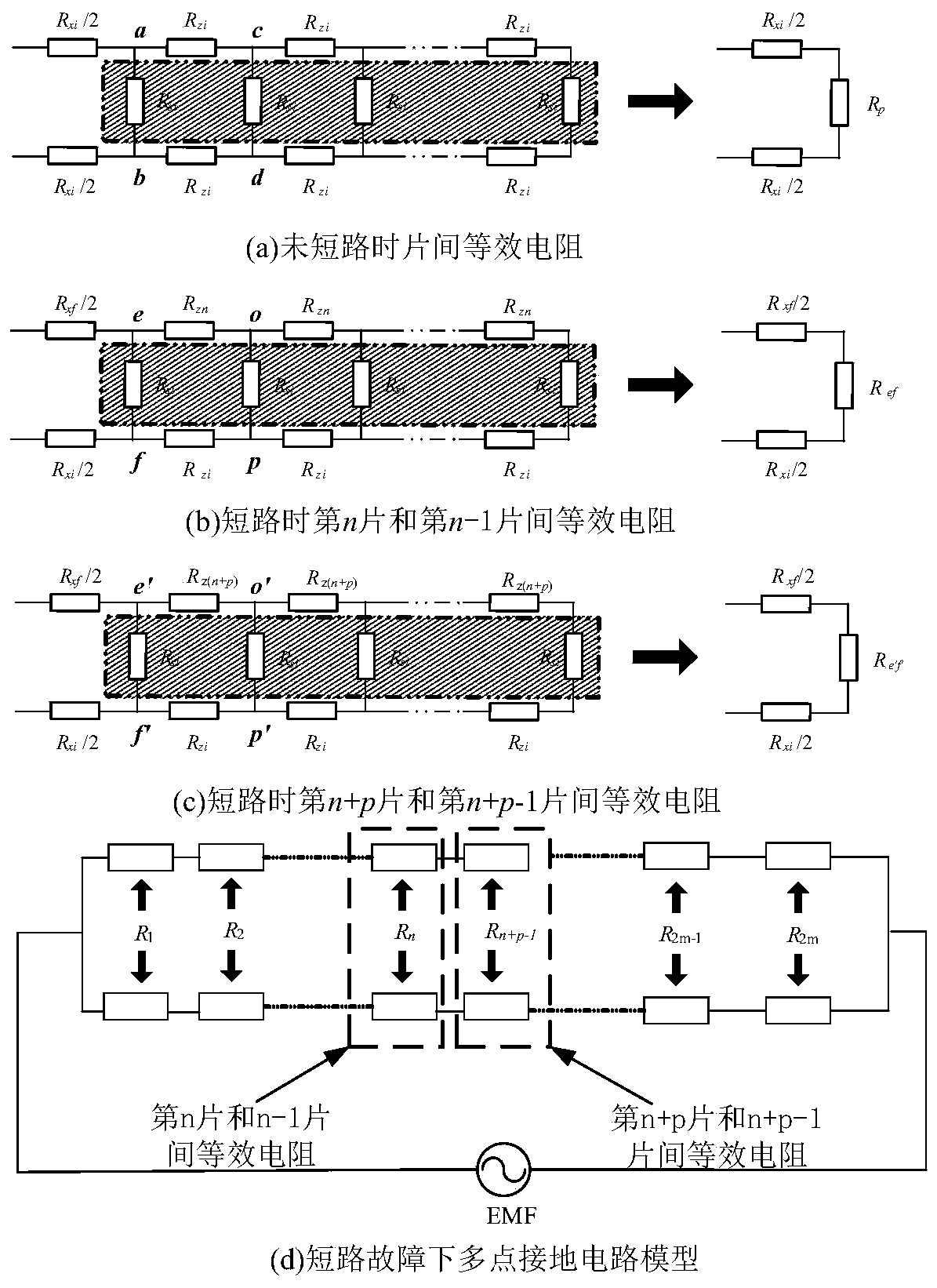
The invention discloses a modeling method for a multi-point grounding fault of a wound core under an inter-sheet short circuit, and the method comprises the steps that a relational expression among the length of a winding path, the width of a section and the number of winding stages of each stage of a silicon steel strip is built under the condition that the geometric parameters of an inner window of the wound core and the radius of an outer section of a core column are known; the sheet-to-sheet equivalent resistance of the wound core is deduced when no short circuit occurs; when inter-chip short circuit occurs, the short-circuit silicon steel sheets are equivalent to one silicon steel sheet, and equivalent resistance between the short-circuit silicon steel sheets and non-short-circuit sheets is derived; according to the obtained equivalent resistance, a wound core multi-point grounding fault circuit model is built, and short circuit and non-short circuit hierarchical total equivalent resistance is derived by using a circuit principle; the fault current of the section where the iron core grounding point is located can form a loop, the potential difference of the grounding point is obtained according to the change rate of the cross-linked magnetic flux in the iron core and the Lenz's law, and the calculated value of the fault grounding current is further obtained.

Description

technical field [0001] The invention belongs to the field of lumped parameter modeling and numerical calculation of transformer iron core equivalent circuit, and specifically relates to a modeling method for multi-point grounding faults of coiled iron core with inter-chip short circuit Background technique [0002] With the vigorous development of high-speed rail, the demand for electric energy is increasing. Due to the small loss of wound core traction transformers, in response to the national call for energy conservation and emission reduction, more and more wound core traction transformers are applied to high-speed rail at this stage. Ensuring the safe operation of the wound core traction transformer plays a key role in the stable operation of the entire traction system, and the wound core is one of the main components of the traction transformer, once a failure occurs, it will seriously affect the normal operation of the transformer. The multi-point grounding of the woun...

Claims


Application Information

Patent Timeline
IPC IPC(8): G06F17/50
CPCG06F30/367
Inventor 高仕斌林桐周利军周祥宇于兴宇陈辰
Owner SOUTHWEST JIAOTONG UNIV
Learn More