
Overload and short circuit protection circuit

A technology for protecting circuits and circuits, which is applied to emergency protection circuit devices, overcurrent-responsive protection, circuit devices, etc. It can solve the problems of no self-recovery, accidents, unsuitable for small volume and high current, etc., and achieves simple structure , the effect of stable function

Pending Publication Date: 2019-09-20
深圳市图灵科创产业发展有限公司
View PDF0 Cites 1 Cited by
  • Summary
  • Abstract
  • Description
  • Claims
  • Application Information

AI Technical Summary

Problems solved by technology

[0002] Electrical fire is the main cause of fire accidents, and overload and short circuit are the main factors leading to electrical fires. When the circuit is overloaded, the current exceeds the current carrying capacity of the wire, which will cause the wire to heat up. When the circuit is short-circuited, the two poles of the circuit Electric sparks are generated in between, if the wires get hot or the electric sparks are not dealt with in time, it may cause accidents
[0003] At present, in order to avoid electrical accidents, AC circuits are usually equipped with circuit protection devices, but most of the existing technologies are passive protection solutions, such as fuses, circuit breakers, etc. However, fuses and circuit breakers in these passive protection solutions are consumables. Without self-recovery function, it is not suitable for electrified products with small volume and high current that require recoverable AC short-circuit protection

Method used


Image

  • Overload and short circuit protection circuit
  • Overload and short circuit protection circuit
  • Overload and short circuit protection circuit

Examples


Embodiment Construction

[0020] The technical solutions of the present invention will be further described in detail below in conjunction with the drawings and specific embodiments of the description.

[0021] Unless otherwise defined, all technical and scientific terms used herein have the same meaning as commonly understood by one of ordinary skill in the technical field of the invention. The terms used herein in the description of the present invention are only for the purpose of describing specific embodiments, and are not intended to limit the protection scope of the present invention. As used herein, the term "and / or" includes any and all combinations of one or more of the associated listed items.

[0022] In the following description, the expression "some embodiments" refers to a subset of all possible embodiments, but it should be understood that "some embodiments" may be the same subset or different subsets of all possible embodiments , and can be combined with each other without conflict. ...


PUM


Abstract

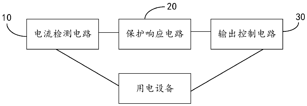
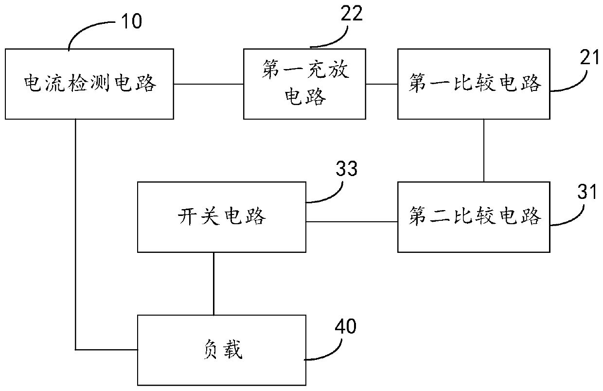
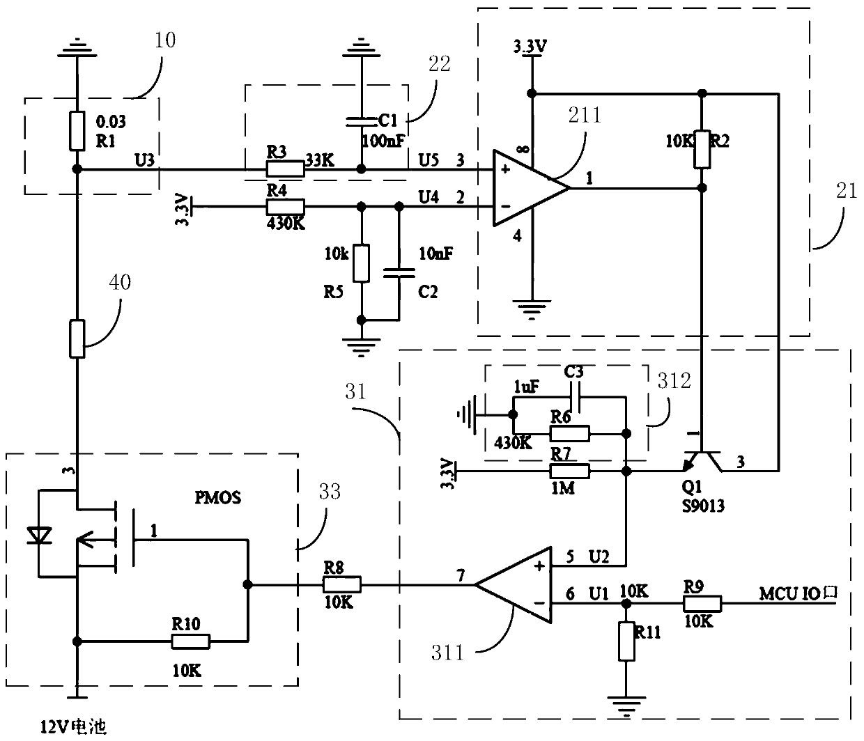
The invention discloses an overload and short circuit protection circuit. A current detection circuit is used to detect a load current flowing through a load. A protection response circuit includes a first charging and discharging circuit connected with the current detection circuit and a first comparison circuit connected with the first charging and discharging circuit. An output control circuit includes a second comparison circuit connected with the first comparison circuit and a switching circuit. When overload or short circuit occurs in the circuit of the load, the load current is higher than the protection starting current, and the first charging and discharging circuit carries out charging until the first comparison circuit outputs a first control signal, so that the second comparison circuit switches off the switching circuit in order to cut off the circuit of the load and enable the circuit of the load to enter a protection mode. After the switching circuit is switched off, the first charging and discharging circuit carries out discharging until the first comparison circuit outputs a second control signal, so that the second comparison circuit switches on the switching circuit in order to switch on the circuit of the load again and enable the circuit of the load to enter a work mode. Thus, when overload or short circuit occurs in the circuit of the load, the protection mechanism can be started automatically and the circuit can be self-recovered without software.

Description

technical field [0001] The invention relates to the technical field of circuit protection, in particular to an overload and short circuit protection circuit. Background technique [0002] Electrical fire is the main cause of fire accidents, and overload and short circuit are the main factors leading to electrical fires. When the circuit is overloaded, the current exceeds the current carrying capacity of the wire, which will cause the wire to heat up. If the electric wire generates heat or the electric spark is not dealt with in time, it may cause an accident. [0003] At present, in order to avoid electrical accidents, AC circuits are usually equipped with circuit protection devices, but most of the existing technologies are passive protection solutions, such as fuses, circuit breakers, etc. However, fuses and circuit breakers in these passive protection solutions are consumables. Without self-recovery function, it is not suitable for electrified products with small volume ...

Claims


Application Information

Patent Timeline
IPC IPC(8): H02H3/08H02H3/093H02H1/00H02H3/06
CPCH02H3/08H02H3/093H02H1/0007H02H3/06
Inventor 向华董朝阳王宏媛李勇刘稼瑾张宝仓郑宇
Owner 深圳市图灵科创产业发展有限公司
Learn More