Fiber laser mode stability monitoring device and method

A fiber laser and monitoring device technology, applied in laser monitoring devices, lasers, laser parts and other directions, can solve the problems of low sensitivity and high cost, and achieve the effect of improving sensitivity, low cost, and avoiding device damage

Inactive Publication Date: 2020-04-28
CHINA WEAPON EQUIP RES INST
View PDF6 Cites 2 Cited by
  • Summary
  • Abstract
  • Description
  • Claims
  • Application Information

AI Technical Summary

Problems solved by technology

The monitoring device or 10,000-frame high-speed camera composed of high-speed detectors, lenses and oscilloscopes is not only expensive, but also has low sensitivity during use

Method used


Image

  • Fiber laser mode stability monitoring device and method
  • Fiber laser mode stability monitoring device and method

Examples


Embodiment 1

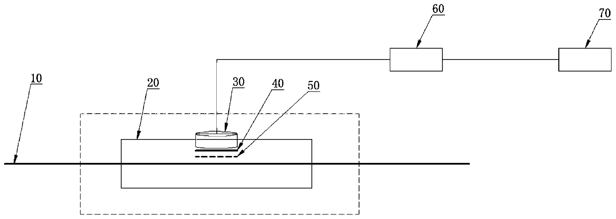
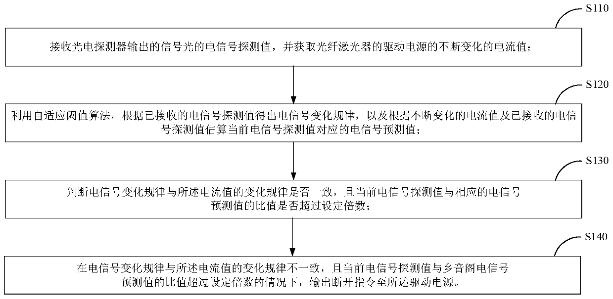
[0066] The monitoring device disclosed in the present invention is used to monitor a high-power narrow-linewidth polarization-maintaining fiber laser; the laser uses a 975nm pump light source, and the output power of the pump light source is greater than 1kw; the fiber uses PM20 / 400 series fiber; the high-power stripper uses It is made of micro-machined corrosion type, and is covered with a glass tube, and a round hole is opened at the upper end of the glass tube; FDS100 or FDS1010 type photodetector is installed in the round hole of the glass tube, and the response band of the photodetector is 400nm~1100nm. The response time is less than 50ns; the light reflectivity of the filter for pump light with a central wavelength of 975nm is greater than 98%, and the transmittance of signal light with a central wavelength of 1064nm is greater than 98%; the attenuation coefficient of the attenuator is 30dB. When the photodetector signal is saturated during the experiment, increase the att...

Embodiment 2

[0069] The monitoring device disclosed in the present invention is used to monitor the high-power thulium-doped fiber laser; the laser uses a 793nm pump light source, and the output power of the pump light source is greater than 1kw; the fiber uses PM25 / 400 series fiber; the high-power stripper uses micro-processing corrosion The FGA20 photodetector is installed in the round hole of the glass tube, and the photodetector has a response band of 1200nm~2600nm, and the response time is less than 50ns; The light reflectivity of the filter for pump light with a central wavelength of 793nm is greater than 98%, and the transmittance of signal light with a central wavelength of 2000nm is greater than 98%; the attenuation coefficient of the attenuator is 30dB. When photoelectricity occurs during the experiment When the detector signal is saturated, the attenuation coefficient of the attenuation sheet is increased to 35dB or 40dB; the control circuit collects the electrical signal of the p...


PUM

PropertyMeasurementUnit
wavelengthaaaaaaaaaa
reflectanceaaaaaaaaaa

Abstract

The invention discloses a fiber laser mode stability monitoring device and method. The monitoring device comprises a photoelectric detector, a filter, an attenuator and a control circuit, wherein a detection end of the photoelectric detector is used for being arranged in a cladding light stripper so as to receive cladding light stripped from an optical fiber by the cladding light stripper; the filter is arranged on the outer side of the detection end and used for filtering pump light in the cladding light; the response wave band of the photoelectric detector comprises a signal light wave band;the attenuator is arranged on one side of the filter and used for attenuating the signal light so as to enable the power of the signal light to be below a saturation threshold of the photoelectric detector; and the control circuit receives an electric signal detection value of the signal light output by the photoelectric detector, acquires a continuously changing current value of a driving powersupply, judges whether the mode of the fiber laser is in a stable state or not, and disconnects the driving power supply of the fiber laser when the judgment result is that the mode is unstable. The monitoring device is low in cost and capable of guaranteeing high sensitivity in the monitoring process.

Description

Technical field [0001] The invention relates to the technical field of fiber lasers, in particular to a fiber laser mode stability monitoring device and method. Background technique [0002] High-power lasers are an important research direction in modern lasers. As a special form of solid-state lasers, fiber lasers have become a very promising laser light source due to their compact structure, high conversion efficiency, and good beam quality. They are used in medicine, communications, radar, sensing, industrial processing, and scientific research. There are a wide range of applications in the field; due to the special advantages of the fiber structure, high-power fiber lasers have received special attention as one of the main development directions of fiber lasers. [0003] High-power fiber lasers have obvious advantages in beam quality, volume, weight, efficiency, heat dissipation, etc., and are now widely used in fiber optic communications, laser space long-distance communicati...

Claims


Application Information

Patent Timeline
Patent Type & Authority Applications(China)
IPC IPC(8): H01S3/067H01S3/00
CPCH01S3/0014H01S3/067
Inventor 李川张志强李晔尹聿海李青松陈园园王彤璐韩松雷婕妤李松柏
Owner CHINA WEAPON EQUIP RES INST
Why Eureka
Try Eureka