Permanent magnet synchronous motor resolver zero position calibration circuit
A permanent magnet synchronous motor, zero calibration technology, applied in motor control, electronic commutation motor control, electrical components and other directions, can solve the problem of inability to adapt to the influence of resolver angle deviation, inability to achieve real-time self-calibration learning, complex implementation, etc. problem, to achieve the effect of small footprint, prevention of zero position change of resolver, and low circuit cost
- Summary
- Abstract
- Description
- Claims
- Application Information
AI Technical Summary
Problems solved by technology
Method used
Image

Examples
Example Embodiment
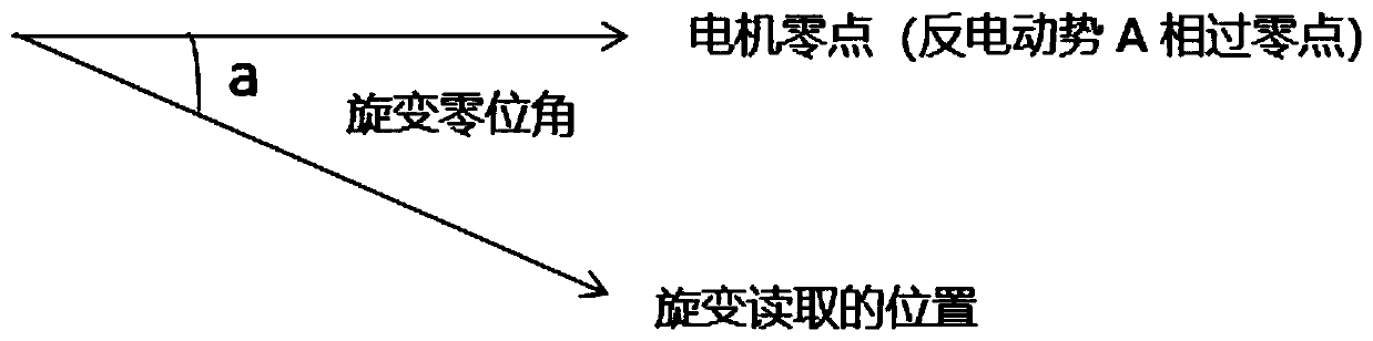
[0024] The principle of the present invention is to determine the current position of the rotor according to the size of the counter electromotive force, such as figure 1 As shown, when phase A descends to the zero point, the rotor is at the 0 degree position (the position of the D axis), when the B phase descends to the zero point, the rotor is at the position of 120 degrees, and when the C phase descends to the zero point, the rotor is at 240 degree position.
[0025] u a =-ωΨ f sin(ωt)
[0026] u b =-ωΨ f sin(ωt-2*π / 3)
[0027] u c =-ωΨ f sin(ωt-4*π / 3)
[0028] Utilizing the characteristics of AD2S1210 resolver decoding chip to update the position information at the falling edge of SAMPLE, the current rotor position is read through AD2S1210 resolver decoding chip when the counter electromotive force crosses zero, so as to obtain the resolver zero angle.
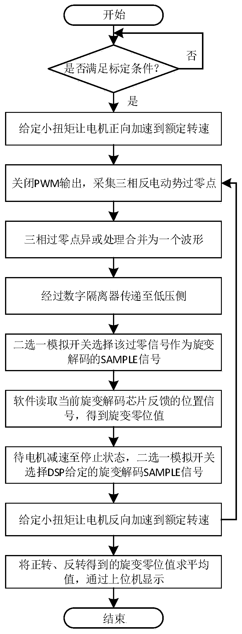
[0029] The specific implementation steps are as figure 2 Shown: First, a small torque is given to accelerate ...
PUM
 Abstract
Description
Claims
Application Information
PatSnap Eureka turns technology decisions into work you can execute. Powered by our Innovation Knowledge Graph, it runs expert workflows across engineering, life sciences, materials and intellectual property. Get your review-ready output in minutes.


