
Loudspeaker

A loudspeaker and bottom surface technology, applied in the field of loudspeakers, can solve problems such as reducing the acoustic performance of products, and achieve the effect of increasing the bonding fastness

Inactive Publication Date: 2019-09-20
AAC TECH PTE LTD
View PDF9 Cites 3 Cited by
  • Summary
  • Abstract
  • Description
  • Claims
  • Application Information

AI Technical Summary

Problems solved by technology

[0004] In the prior art loudspeaker, the loudspeaker is deeply waterproof. After the front cover and the diaphragm are glued together, the excess diaphragm material will be cut off along the outer edge of the front cover so that the outer edge of the diaphragm is flush with the outer edge of the front cover, while In order to realize the deep waterproof between the front cover and the diaphragm, it is generally achieved by increasing the width of the glued surface between the end face of the front cover and the end face of the diaphragm, which will reduce the acoustic performance of the product

Method used


Image

  • Loudspeaker
  • Loudspeaker
  • Loudspeaker

Examples


Embodiment 1

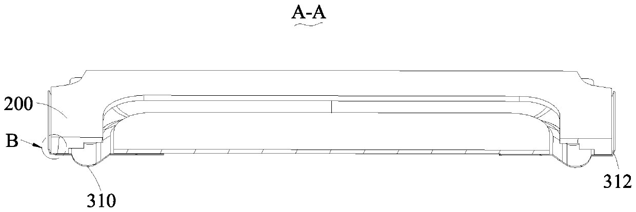
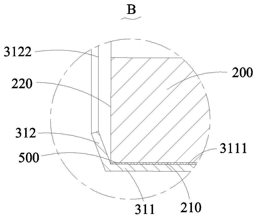
[0041] see Figure 1-10 , the loudspeaker provided by the embodiment of the present invention includes a basin frame 100, a front cover 200, a vibration system 300 and a magnetic circuit system 400, the basin frame has a storage space 120, the vibration system 300 and the magnetic circuit system 400 are accommodated in the storage space 120, the vibration system 300 includes a diaphragm 310 fixed on the frame 100 and a voice coil 320 supported on one side of the diaphragm 310 , the front cover 200 is stacked on the diaphragm 310 , and the diaphragm 310 is disposed between the front cover 200 and the frame 100 . The magnetic circuit system 400 includes a magnetic bowl 410 fixed on the side of the basin frame 100 away from the diaphragm 310, and a main magnet 420 and a side magnet 430 fixed to the magnetic bowl 410. The side magnets 430 are located on opposite sides of the main magnet 420. The side and the main magnetic steel 420 are spaced apart to form a magnetic gap 440 , and...

Embodiment 2

[0056] refer to Figure 11-13 As shown, the difference between the loudspeaker provided in this embodiment and the first embodiment lies in the structure of the front cover 200, which is specifically reflected in: in this embodiment, the bottom surface 210 of the front cover 200 is provided with several grooves distributed at intervals 230, the adhesive layer 500 is further filled between the groove 230 and the adhesive surface 3111, the adhesive layer 500 specifically includes the first adhesive layer 510 filled between the adhesive surface 3111 and the bottom surface 210 and the first adhesive layer 510 filled on the adhesive surface 3111 and the second adhesive layer 520 between the groove 230 . The groove 230 is specifically recessed and formed from the bottom surface 210 toward a direction away from the bonding portion 311 . In this embodiment, the vibrating membrane 310 is provided with a groove 230 on the bottom surface 210 of the front cover 200 for bonding with the v...

Embodiment 3

[0063] refer to Figure 14 and Figure 15 As shown, the difference between the speaker and the mobile terminal device provided by this embodiment and the second embodiment is mainly that the arrangement of the groove 230 is different, which is specifically reflected in: in this embodiment, the groove 230 is arranged around the bottom surface 210 And the annular groove is arranged at intervals between the outer ring edge 211 and the inner ring edge 212 , and the adhesive layer is further filled between the annular groove and the bonding part. The arrangement of the annular groove in this embodiment can also achieve the purpose of further increasing the amount of local glue between the front cover 200 and the diaphragm and improving the deep waterproof performance without reducing the acoustic performance of the product.


PUM


Abstract

The invention provides a loudspeaker which comprises a basin frame, a front cover and a vibration system, the vibration system comprises a vibrating diaphragm, the front cover comprises a bottom surface opposite to the vibrating diaphragm, a top surface opposite to the bottom surface and an outer side surface connected between the top surface and the bottom surface, and the basin frame comprises a supporting surface right opposite to the bottom surface and an extending surface which is bent and extends towards the direction of the front cover from the supporting surface; wherein the vibrating diaphragm comprises a bonding part and a flanging formed by folding from the edge of the bonding part, the bonding part is provided with a bonding surface which is separated from and opposite to the bottom surface, the flanging is positioned between the extending surface and the outer side surface, and the loudspeaker also comprises an adhesive layer clamped between the bonding surface and the bottom surface, and a sealant filled between the outer side surface and the flanging. The vibrating diaphragm is provided with the flanging folded on the outer side of the outer side surface of the front cover, and the sealant is filled between the flanging and the outer side surface, so that the gluing area between the front cover and the vibrating diaphragm is equivalently increased, the purpose of deep waterproofing is achieved, and meanwhile, the acoustic performance of a product is not reduced.

Description

[0001] 【Technical field】 [0002] The invention relates to the field of sound and electricity, in particular to a loudspeaker. [0003] 【Background technique】 [0004] In the prior art loudspeaker, the loudspeaker is deeply waterproof. After the front cover and the diaphragm are glued together, the excess diaphragm material will be cut off along the outer edge of the front cover so that the outer edge of the diaphragm is flush with the outer edge of the front cover, while In order to achieve deep waterproofing between the front cover and the diaphragm, it is generally achieved by increasing the width of the glued surface between the end face of the front cover and the end face of the diaphragm, which will reduce the acoustic performance of the product. [0005] Therefore, it is necessary to provide a new loudspeaker to solve the above technical problems. [0006] 【Content of invention】 [0007] The purpose of the present invention is to provide a loudspeaker, which can achiev...

Claims


Application Information

Patent Timeline
Patent Type & Authority Applications(China)
IPC IPC(8): H04R9/06H04R9/02
CPCH04R9/025H04R9/06H04R2400/11
Inventor 张古清
Owner AAC TECH PTE LTD
Learn More