Bearing ring automatic machining equipment

A technology for automatic processing and bearing rings, applied in the field of bearing processing, can solve the problems of excessive variation in the inner diameter/outer diameter of a single plane, low qualified rate of semi-finished turning parts, and difficulty in adjusting the clamping force, so as to increase practical performance, Uniform pressure to avoid excessive effect

Active Publication Date: 2019-09-24
临清市毅轩轴承有限公司
View PDF7 Cites 4 Cited by
  • Summary
  • Abstract
  • Description
  • Claims
  • Application Information

AI Technical Summary

Problems solved by technology

[0002] Due to the large diameter and thin wall thickness of the ferrule of extra-large thin-walled bearings, the claws clamp the ferrule too tightly during lathe processing, and the ferrule is deformed. Generally, four-jaw single-action chucks are commonly used in the processing process. Made of carbon tool steel, the contact area with the ferrule is small, and the clamping force is not easy to adjust. It is not suitable for extra-large thin-walled bearings. If it is used hard, there will be serious variations in the inner diameter / outer diameter of a single plane. The qualified rate of semi-finished turning parts is low

Method used


Image

  • Bearing ring automatic machining equipment
  • Bearing ring automatic machining equipment
  • Bearing ring automatic machining equipment

Examples


Embodiment

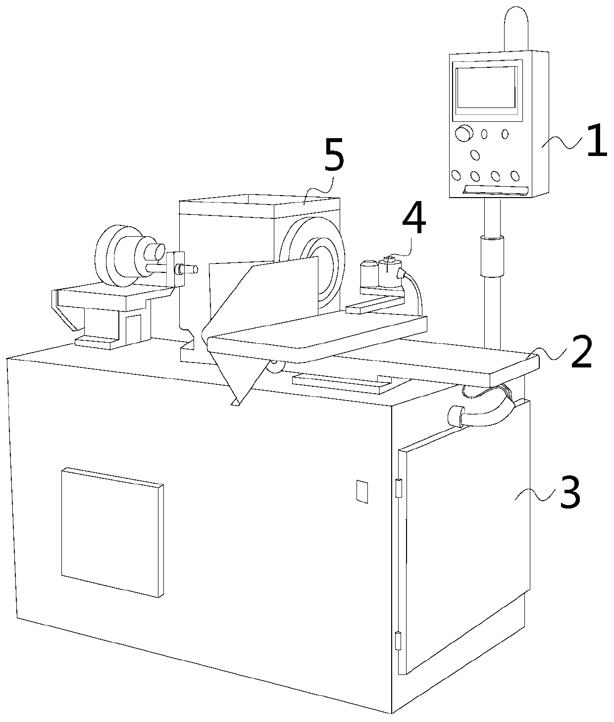
[0027] see Figure 1-Figure 6 , the present invention provides an automatic processing equipment for bearing rings, the structure of which includes a controller 1, an operating table 2, a body 3, a tool 4, a soft claw disk mounting seat 5, and a soft claw disk 6. The top surface of the body 3 is provided with a There is an operation table 2, and the other end is installed with a soft claw disk mounting seat 5, and the soft claw disk mounting seat 5 is movable with a soft claw disk 6, and a controller 1 is installed side by side on the body 3 on one side of the operation table 2 And a cutter 4, the cutter 4 is located between the soft claw plate mounting seat 5 and the controller 1.

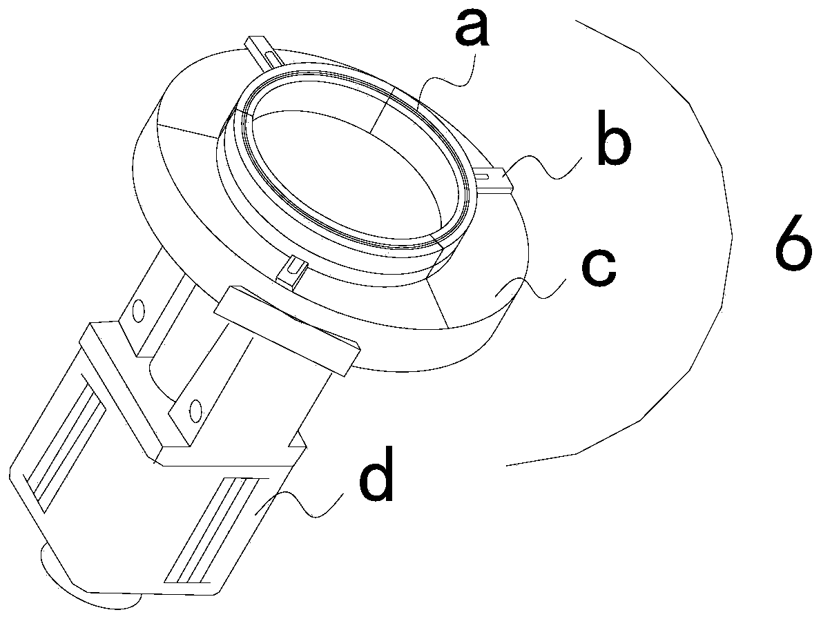
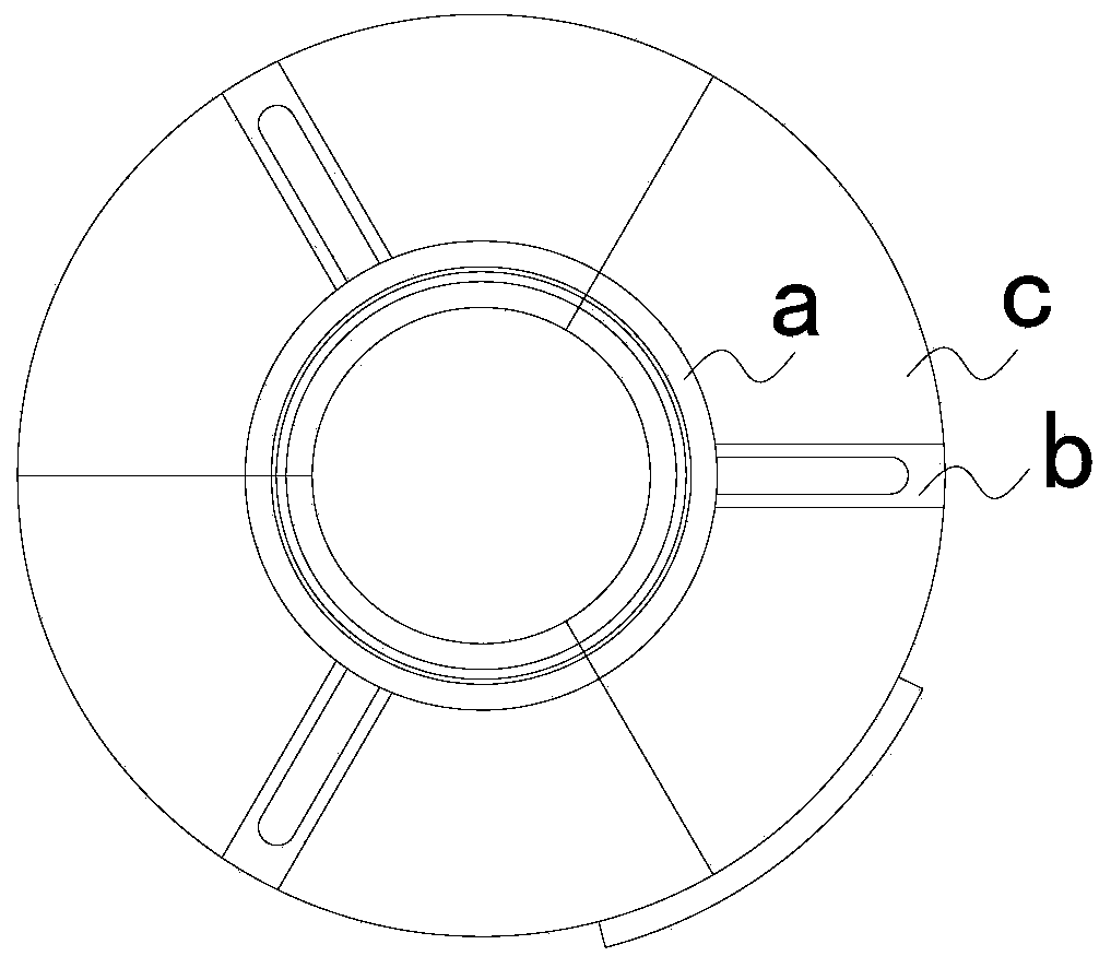
[0028] The soft claw disc 6 is composed of claw a, sliding seat b, claw body c, and motor d. The motor d is located directly below the claw body c. There are three claw bodies c, and the three claw bodies c are adjacent to each other. The two will be joined together to form a complete circle. The...


PUM


Abstract

The invention discloses bearing ring automatic machining equipment. The equipment structurally comprises a controller, an operating console, a body, a tool, a soft claw disc mounting base and a soft claw disc. The operating console is arranged at one end of the top end surface of the body, and the soft claw disc mounting base is mounted at the other end of the top end surface of the body. The soft claw disc is movably mounted on the soft claw disc mounting base. The controller and the tool are mounted on the portion, located at one side of the operating console, of the body in parallel. The tool is located between the soft claw disc mounting base and the controller. The soft claw disc is composed of a claw, a sliding base, a claw body and a motor. The motor is located under the claw body. According to the bearing ring automatic machining equipment, through cooperation of the claw, the claw body, the motor and the like, on the one hand, a circular truncated cone is made to rise and fall continuously by means of forward and reverse rotating of the motor, meanwhile, the contact area is further increased through uniform three-point force application and an L-type structure and a piston of the claw, the clamping stability and the adjusting convenience are improved, and it is guaranteed that no single plane inner diameter/outer diameter variation deviation occurs when an extra-large thin-wall bearing is machined.

Description

technical field [0001] The invention relates to the field of bearing processing, in particular to an automatic processing equipment for bearing rings. Background technique [0002] Due to the large diameter and thin wall thickness of the ferrule of extra-large thin-walled bearings, the claws clamp the ferrule too tightly during lathe processing, and the ferrule is deformed. Generally, four-jaw single-action chucks are commonly used in the processing process. Made of carbon tool steel, the contact area with the ferrule is small, and the clamping force is not easy to adjust. It is not suitable for extra-large thin-walled bearings. If it is used hard, there will be serious variations in the inner diameter / outer diameter of a single plane. The qualified rate of semi-finished turning parts is low. Contents of the invention [0003] Aiming at the deficiencies of the prior art, the present invention is realized through the following technical solutions: an automatic processing e...

Claims


Application Information

Patent Timeline
Patent Type & Authority Applications(China)
IPC IPC(8): B23B5/00B23B7/14B23B31/103
CPCB23B5/00B23B7/12B23B31/103
Inventor 李斌王清常骆洪宇
Owner 临清市毅轩轴承有限公司
Why Eureka
Try Eureka