
An art printing machine

A printing machine and printing technology, which is applied to printing machines, rotary printing machines, printing, etc., can solve the problems of increasing equipment maintenance costs, increasing equipment costs, and complicated work processes, so as to improve printing efficiency, avoid performance limitations, and ensure The effect of printing effect

Active Publication Date: 2020-11-10
SHANGQIU NORMAL UNIVERSITY
View PDF1 Cites 0 Cited by
  • Summary
  • Abstract
  • Description
  • Claims
  • Application Information

AI Technical Summary

Problems solved by technology

[0002] In the process of industrial production, art printing is usually required. Art printing can make industrial products more beautiful and facilitate marketing. The existing printing mechanism is generally semi-automatic, requiring manual participation, and the structure is complex. The application number is 201510179873.8 Invention patent Disclosed is an automatic printing machine, which can be automatically completed from conveying to positioning to printing end to output, replacing manual operation to realize mechanization and automation, improving efficiency, reducing cost, improving product quality, and reducing the risk of manual operation in the production process. However, the entire workflow requires positioning sensors and printing sensors. On the one hand, sensor signal transmission has a certain delay and error, and excessive use of sensors increases equipment costs, and sensor replacement increases equipment maintenance costs. On the one hand, in the streamlined printing process, the positioning arm needs to rotate repeatedly to compress the glass bottle, and the working process is complicated. Therefore, the art printing machine used in industrial production needs to be further improved to improve the working efficiency of the printing machine and reduce the cost of use.

Method used


Image

  • An art printing machine
  • An art printing machine
  • An art printing machine

Examples


Embodiment Construction

[0017] The technical solutions in the embodiments of the present invention will be clearly and completely described below in conjunction with the accompanying drawings in the embodiments of the present invention. Obviously, the described embodiments are only some of the embodiments of the present invention, not all of them. Based on The embodiments of the present invention and all other embodiments obtained by persons of ordinary skill in the art without making creative efforts belong to the protection scope of the present invention.

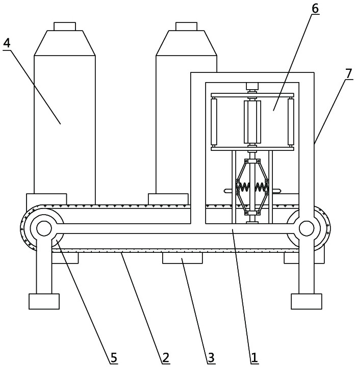
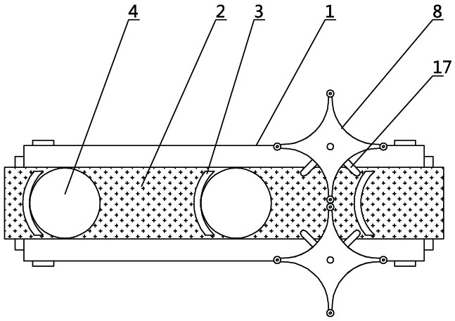
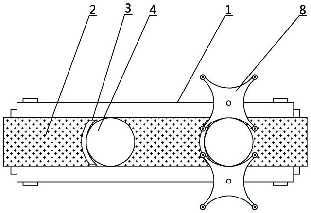
[0018] see Figure 1-6 , the present invention provides a technical solution: an art printing machine, including a conveyor belt 2 and two printing mechanisms 6 located at symmetrical positions on both sides of the conveyor belt 2, the conveyor belt 2 is connected to the transmission wheel 5 on the base 1, and the conveyor belt 2 arc-shaped baffles 3 are evenly distributed on the sides, and glass bottles 4 are placed on the right side of each ba...


PUM


Abstract

The invention discloses an art printing machine. The art printing machine comprises a conveyor belt and two printing mechanisms positioned at symmetric positions on the front side and the rear side of the conveyor belt, wherein the conveyor belt is used for mass movement of a glass bottle, when the glass bottle is in contact with a transverse push plate, blocking pieces are arranged on the conveyor belt, when the glass bottle is in contact with a transverse pushing rod to push the transverse pushing rod, the reaction force of the transverse pushing rod pushes the glass bottle, so that the glass bottle abuts against the blocking pieces, the blocking pieces uniformly distributed on the conveyor belt so as to enable the glass bottles to be uniformly distributed, the printing work of a printing stamp is facilitated, the transverse push rod pushes a lock rod in the process that the transverse push rod is pushed by the glass bottles, the upper end of the lock rod leaves the outer convex part of a flower-shaped groove, a second rotary disc unlocking starts to rotate, the printing stamp is used for carrying out printing work on the side surface of the glass bottles, the opening of the printing stamp is controlled by the glass bottles pushing the transverse pushing rod, and the precision and reliability are achieved.

Description

technical field [0001] The invention belongs to the technical field of printing machine equipment, and in particular relates to an art printing machine. Background technique [0002] In the process of industrial production, art printing is usually required. Art printing can make industrial products more beautiful and facilitate marketing. The existing printing mechanism is generally semi-automatic, requiring manual participation, and the structure is complex. The application number is 201510179873.8 Invention patent Disclosed is an automatic printing machine, which can be automatically completed from conveying to positioning to printing end to output, replacing manual operation to realize mechanization and automation, improving efficiency, reducing cost, improving product quality, and reducing the risk of manual operation in the production process. However, the entire workflow requires positioning sensors and printing sensors. On the one hand, sensor signal transmission has ...

Claims


Application Information

Patent Timeline
Patent Type & Authority Patents(China)
IPC IPC(8): B41F16/00B41F17/18
CPCB41F16/00B41F17/18
Inventor 余航孟星星
Owner SHANGQIU NORMAL UNIVERSITY
Learn More