
Self-locking type box overturning machine

A self-locking, box-turning machine technology, applied in the direction of conveyor objects, emptying containers, loading/unloading, etc., can solve the high cost of use and maintenance of four cylinders, poor synchronization of four cylinders, and cannot be guaranteed Clamping force and other issues, to achieve the effect of flexible turning, simple structure, stable and consistent clamping force

Pending Publication Date: 2019-09-24
KUNMING XUBANG MACHINERY
View PDF1 Cites 2 Cited by
  • Summary
  • Abstract
  • Description
  • Claims
  • Application Information

AI Technical Summary

Problems solved by technology

Chinese patent 200420008223.4 discloses a kind of " box turning machine ", although it can realize the 180 ° turning over of box, because this box turning machine adopts four cylinders to vertically lift the box conveyor to clamp the box, and then completes turning over Box action, the shortcomings of this method are: the synchronization of the four cylinders is not good, there is no locking function after the box is clamped, and it cannot guarantee a stable and consistent clamping force during the entire flipping process. If there is a power failure, If the air is cut off or the electrical components fail, there will be a problem of material scattering in the box; the use cost and maintenance cost of the four cylinders are high

Method used


Image

  • Self-locking type box overturning machine
  • Self-locking type box overturning machine
  • Self-locking type box overturning machine

Examples


Embodiment Construction

[0015] The present invention will be further described below in conjunction with the accompanying drawings.

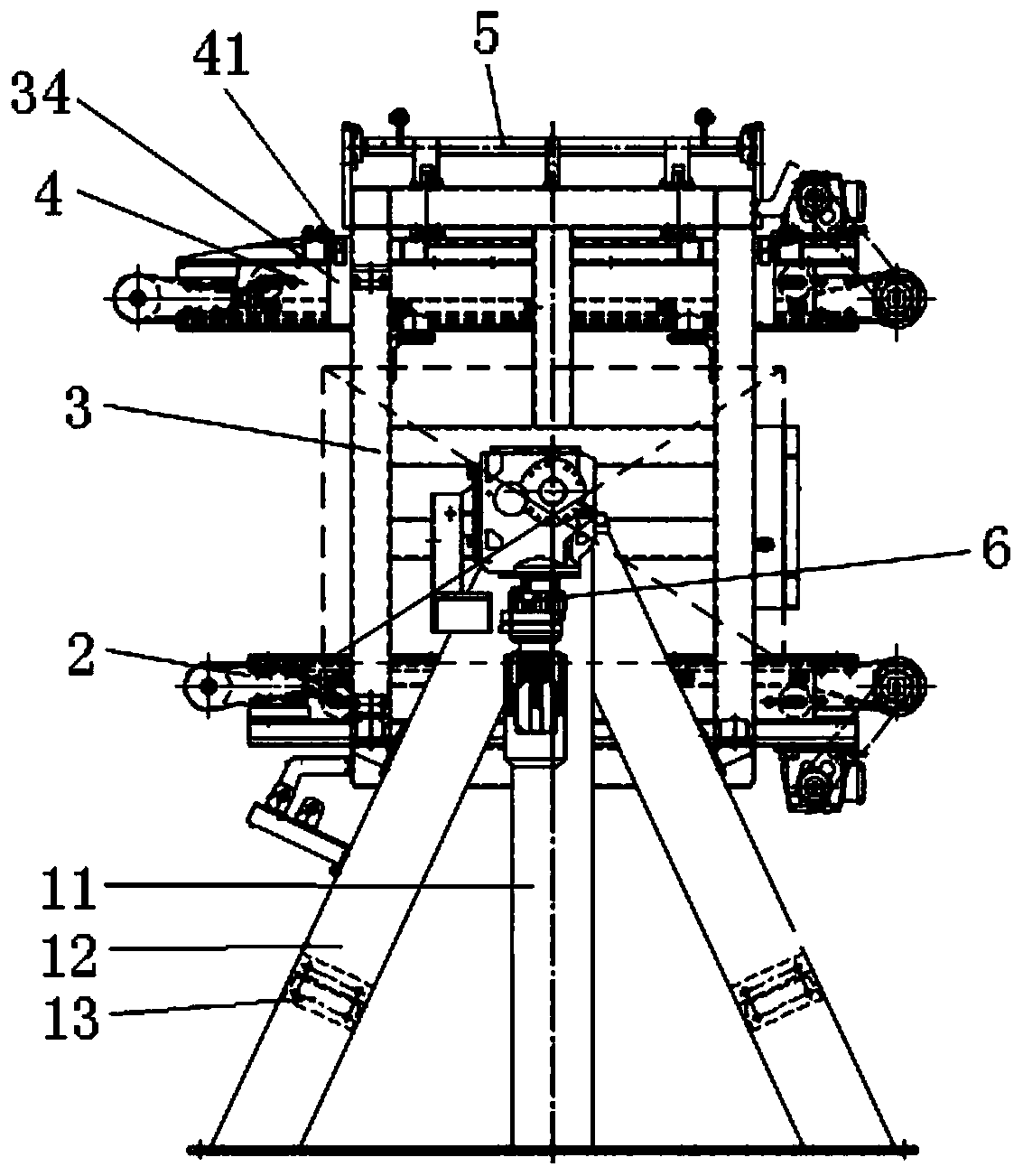
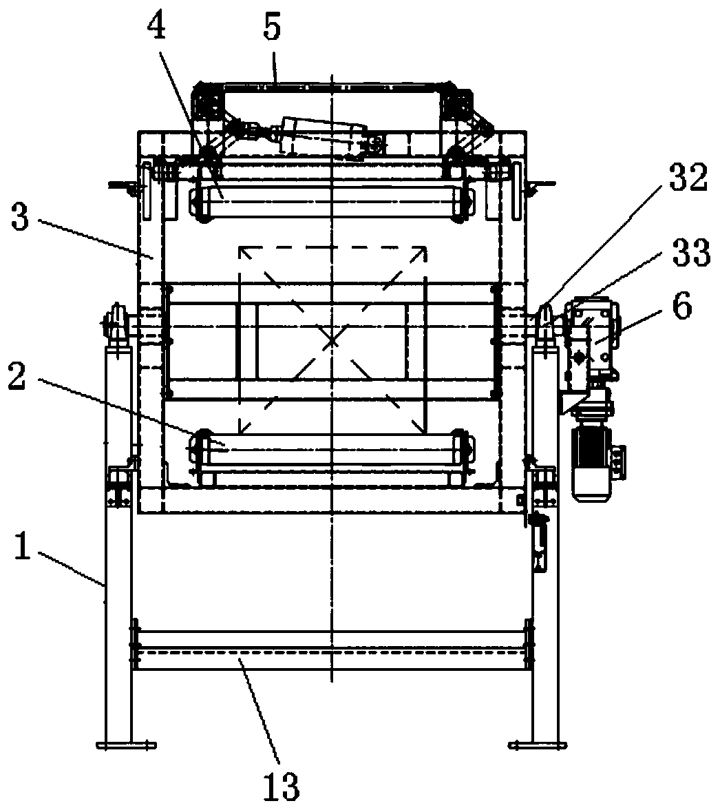
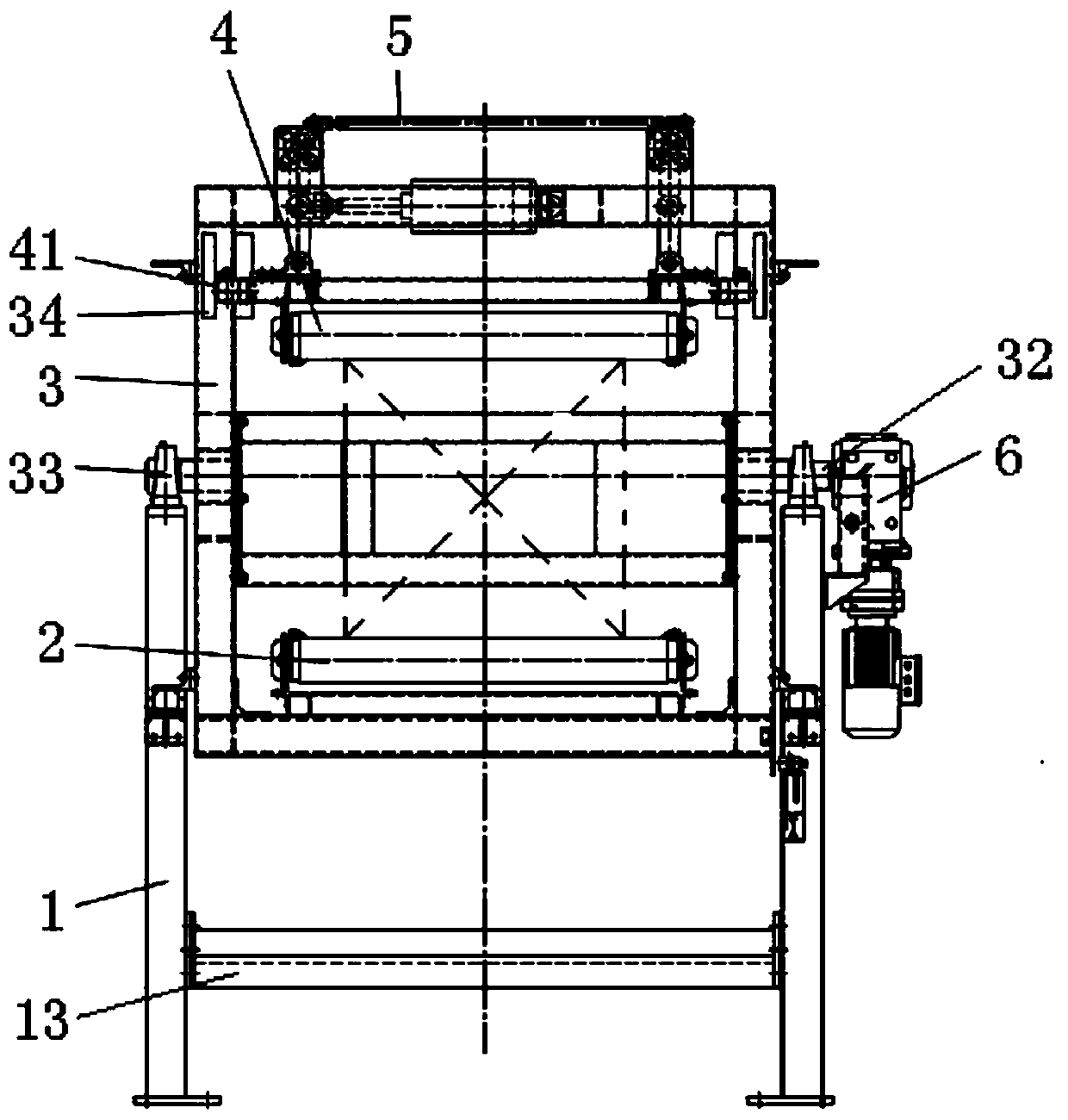
[0016] The self-locking box turning machine provided by the present invention includes a support frame 1, a rotating frame 3, and two conventional conveyors, one of which is a box-in conveyor 2, and the other is a box-out conveyor 4, both of which are belt conveyors. machine, on the supporting frame 1 is provided with a rotating frame 3, and the entering and exiting conveyors 2 and 4 are symmetrically arranged on the rotating frame 3, and the conveying surfaces of the entering and exiting conveyors 2 and 4 are arranged opposite to each other, and The box conveyor 4 is fixed on the rotating frame 3 through a self-locking synchronous lifting mechanism 5; wherein:

[0017] The swivel frame 3 includes a rectangular frame, two short shafts 32 are respectively arranged in the middle of both sides of the rectangular frame, and the outer ends of the two short shafts 32 are res...


PUM


Abstract

The invention provides a self-locking type box overturning machine. A supporting frame, a rotating frame and conveyors are included. The self-locking type box overturning machine is characterized in that the rotating frame is arranged on the supporting frame, and symmetrically provided with the box entering and box outgoing conveyors; the conveying faces of the box entering and box outgoing conveyors are arranged in opposite directions; and the box outgoing conveyor is fixed to the rotating frame through a self-locking type synchronous lifting mechanism. After a box conveniently enters the box entering conveyor, the box outgoing conveyor is driven by the self-locking type synchronous lifting mechanism to stretch out so that the conveying face of the box outgoing conveyor can clamp the box; then along with rotation of the rotating frame, after the box entering and box outgoing conveyors and the box are overturned by 180 degrees, the box outgoing conveyor is driven by the self-locking type synchronous lifting mechanism to retract out so that clamping on the box can be released, and then the box overturned by 180 degrees is conveyed out through the box outgoing conveyor. The box overturning machine can be used for stably clamping the box, clamping and stretching and retracting are synchronous, mechanical self locking is achieved, it is guaranteed that the box keeps a consistent clamping force in the whole overturning process, the problem that due to the fact that clamping is not stable, after the box is loose, materials are scattered is solved, the structure is simple, clamping is reliable, and overturning is flexible.

Description

technical field [0001] The invention relates to a box turning machine, in particular to a mechanical self-locking box turning machine, which belongs to the technical field of design and manufacture of mechanical turning equipment. Background technique [0002] In the process of industrialized production, many products or materials are mostly packed in boxes. For bulk materials contained in large boxes, if these bulk materials are manually taken out from the box, it is not only inefficient, but also labor-intensive. However, mechanically turning the opened box 180° so that the mouth of the box faces down and the bottom of the box faces up, and then the box is taken away by the manipulator, can solve the problems of low work efficiency and high labor intensity. Chinese patent 200420008223.4 discloses a kind of " box turning machine ", although it can realize the 180 ° turning over of box, because this box turning machine adopts four cylinders to vertically lift the box convey...

Claims


Application Information

Patent Timeline
Patent Type & Authority Applications(China)
IPC IPC(8): B65G65/23B65G47/248
CPCB65G65/23B65G47/248
Inventor 王晓耕尹恒
Owner KUNMING XUBANG MACHINERY
Learn More