Steel rope anchor bolt

A technology of steel cables and anchor bolts, which is applied in the direction of transmission elements or pulley ropes or cables, pins, connecting components, etc., which can solve the problems of high cost, bending of rod-shaped objects, cumbersome operation, etc., so as to improve the anti-loosening effect and increase The effect of friction

Pending Publication Date: 2019-09-24
YIZHONG CONSTR GRP CO LTD
View PDF7 Cites 0 Cited by
  • Summary
  • Abstract
  • Description
  • Claims
  • Application Information

AI Technical Summary

Problems solved by technology

[0002] During the construction of construction projects, occasions where anchor bolts need to be installed are often encountered. The existing anchor bolts are generally fixed by chemical anchor bolts or fixed by expansion bolts, and chemical anchor bolts need to be placed with chemical hoses when they are used. The curing time of the agent is long, and the operation is cumbersome; the expansion anchor is often expanded and fixed by the expansion cylinder and the expansion head, but the expansion process needs to be realized by the rotation of the bolt, and the operation is also cumbersome; due to the existing chemical anchor and expansion anchor. The tension bodies are all rod-shaped objects, and if they need to be connected to the steel cables after they are fixed, additional joints connected to the steel cables need to be installed, resulting in problems of large size, high cost, and complicated operation. If it is changed, it will also cause the rod to bend, and metal fatigue will easily cause the rod to cause engineering accidents over time.

Method used


Image

  • Steel rope anchor bolt
  • Steel rope anchor bolt
  • Steel rope anchor bolt

Examples


Embodiment Construction

[0034] The specific implementation manners of the present invention will be further described in detail below in conjunction with the accompanying drawings and embodiments. The following examples are used to illustrate the present invention, but are not intended to limit the scope of the present invention.

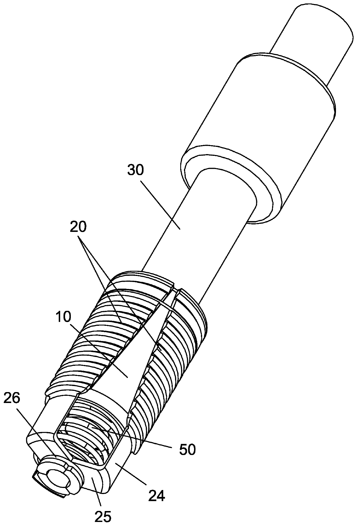
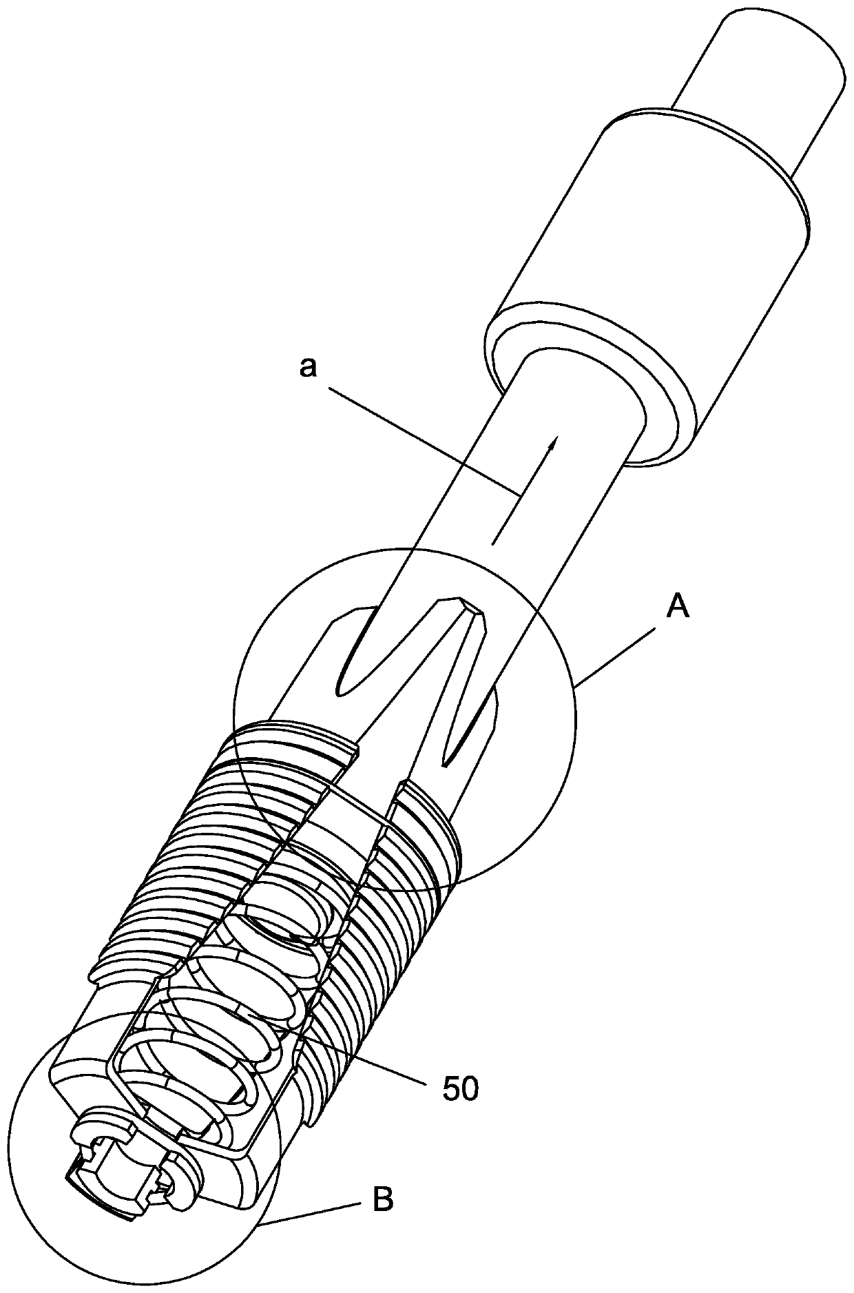
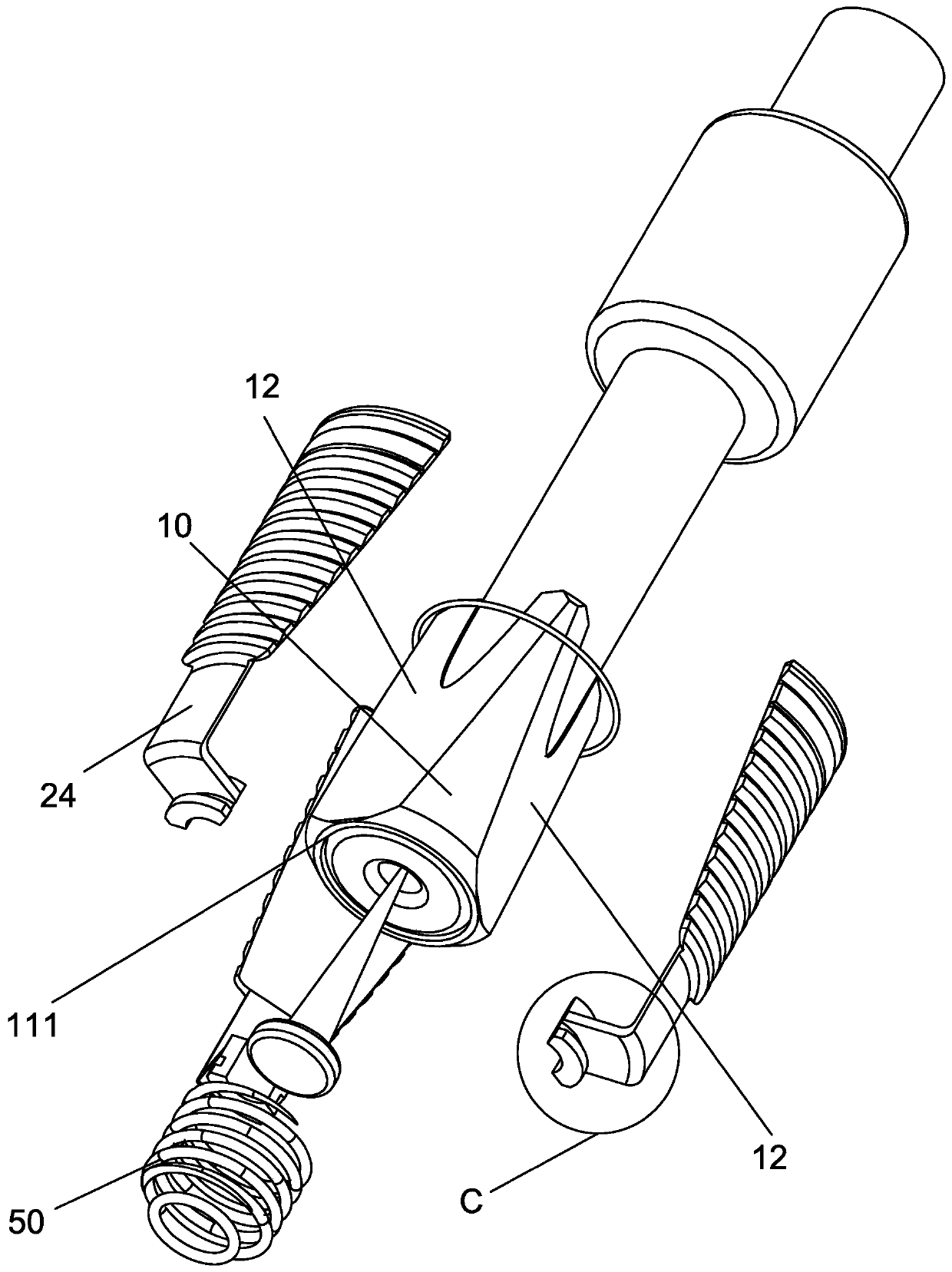
[0035] refer to Figure 1 to Figure 8 ,Such as Figure 1 to Figure 8 The shown cable anchor bolt includes a cylindrical expansion head 10, and the center of the expansion head 10 is provided with a through hole 11, and its outer cylindrical wall is provided with three wedge-shaped surfaces uniformly distributed along its circumferential direction. 12. The tapered tip formed by the virtual extension end of the wedge-shaped surface 12 toward the axial direction of the expansion head 10 faces the tension direction; 12 close to the wedge-shaped block 20, the side of the wedge-shaped block 20 facing away from the wedge-shaped surface 12 fits the outer cylindrical wall contour...


PUM


Abstract

The invention provides a steel rope anchor bolt. The steel rope anchor bolt comprises a cylindrical expansion head, wherein a through hole is formed in the center of the expansion head, three wedge-shaped surfaces which are uniformly distributed in the circumferential direction of the expansion head are arranged on the outer cylindrical wall of the expansion head, and a conical tip formed by virtual extension ends, facing the expansion head in the axial direction, of the wedge-shaped surfaces face a pulling direction; and wedge-shaped blocks are arranged on the wedge-shaped surfaces, one faces, away from the wedge-shaped surfaces, of the wedge-shaped blocks are attached to an outer cylindrical wall contour in front of the wedge-shaped surface of the expansion head, a plurality of saw tooth grooves which are arranged at equal intervals in the axial direction of the expansion head are arranged on one face, opposite to the wedge-shaped surfaces, of the wedge-shaped blocks, the sawtooth tooth tips of the saw tooth grooves face a tension direction, a main outer groove which is formed between the two saw tooth grooves is further formed in one face, opposite to the corresponding wedge-shaped surface, of each wedge-shaped block, and the main outer grooves of the three wedge-shaped blocks are sleeved with main elastic shrinkage rings when the three wedge-shaped surfaces of the expansion head are provided with the wedge-shaped blocks. The steel rope anchor bolt has the advantages of being high in integration degree, firm and reliable in fixation, smooth in placement and sensitive in locking.

Description

technical field [0001] The invention relates to the construction field, in particular to a steel cable anchor bolt. Background technique [0002] During the construction of construction projects, occasions where anchor bolts need to be installed are often encountered. The existing anchor bolts are generally fixed by chemical anchor bolts or fixed by expansion bolts, and chemical anchor bolts need to be placed with chemical hoses when they are used. The curing time of the agent is long, and the operation is cumbersome; the expansion anchor is often expanded and fixed by the expansion cylinder and the expansion head, but the expansion process needs to be realized by the rotation of the bolt, and the operation is also cumbersome; due to the existing chemical anchor and expansion anchor. The tension bodies are all rod-shaped objects, and if they need to be connected to the steel cables after they are fixed, additional joints connected to the steel cables need to be installed, re...

Claims


Application Information

Patent Timeline
Patent Type & Authority Applications(China)
IPC IPC(8): F16B13/06F16G11/04E04G23/02
CPCE04G23/0218F16B13/063F16G11/044
Inventor 潘一中范继群苏立财余益郑丽勤
Owner YIZHONG CONSTR GRP CO LTD
Why Eureka
Try Eureka