Engineering machinery, engine and piston cooling mechanism thereof

A piston cooling and engine technology, which is applied in the direction of engine cooling, machine/engine, engine components, etc., can solve problems such as cylinder knocking, knocking, and tile phenomenon, and achieve the goal of reducing gaps, reducing noise and knocking Effect

Inactive Publication Date: 2011-04-20
WEICHAI POWER CO LTD
View PDF3 Cites 2 Cited by
  • Summary
  • Abstract
  • Description
  • Claims
  • Application Information

AI Technical Summary

Problems solved by technology

[0009] During the working process of the engine, with the movement of the piston and the rotation of the crankshaft, the piston cooling nozzle continuously sprays oil into the piston to cool the piston; however, when the engine speed is low (especially when idling), the engine's The temperature is generally low. At this time, if it is cooled, it is easy to cause insufficient expansion of the piston and piston ring, so that the gap between the piston and the cylinder liner cannot be eliminated, resulting in knocking and cylinder knocking; on the other hand , the cooling engine oil may escape into the combustion chamber to participate in the combustion, but due to its characteristics, it cannot be fully burned, thus forming carbon deposits, and even causing cylinder scuffing; furthermore, due to the pumping volume of the engine oil It is also affected by the rotation speed. When the rotation speed is low, the pumping volume is also small. In this case, the piston cooling nozzle, as an oil leakage point, will inevitably further reduce the oil pressure, so that the lubrication of the bearing bush and other parts is insufficient, resulting in chemical occurrence of tile phenomenon

Method used


Image

  • Engineering machinery, engine and piston cooling mechanism thereof
  • Engineering machinery, engine and piston cooling mechanism thereof
  • Engineering machinery, engine and piston cooling mechanism thereof

Examples


Embodiment Construction

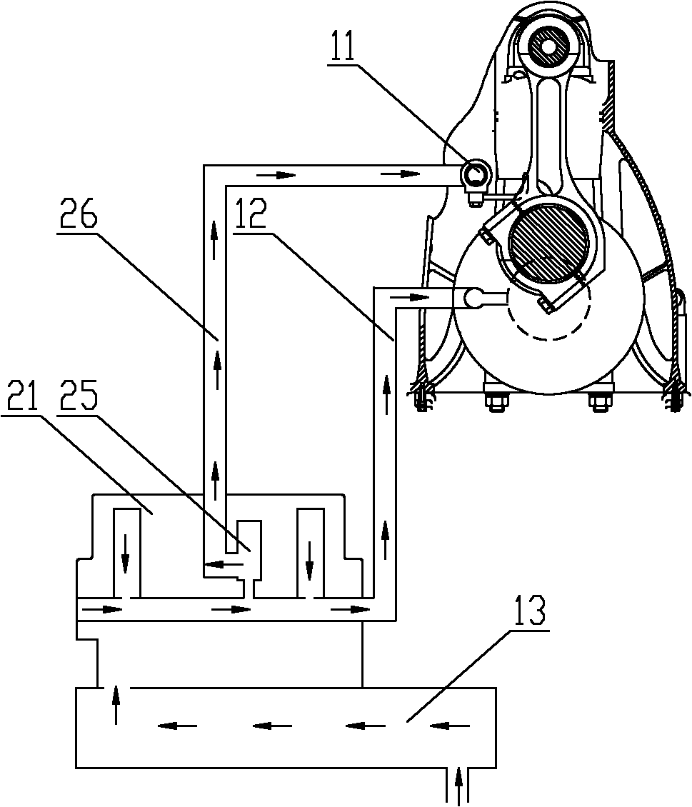
[0028] The core of the present invention is to provide a piston cooling mechanism of the engine, which can control the cooling nozzle to spray engine oil according to the needs, and avoid affecting the expansion of the piston and piston ring under the condition of meeting the cooling requirements, and the cooling oil does not Complete combustion forms carbon deposits. Another core of the present invention is to provide an engine including the piston cooling mechanism of the above-mentioned engine and a construction machine including the above-mentioned engine.

[0029] In order to enable those skilled in the art to better understand the solution of the present invention, the present invention will be further described in detail below in conjunction with the accompanying drawings and specific embodiments.

[0030] Please refer to figure 1 , figure 1 It is a schematic structural diagram of a piston cooling mechanism of an engine provided by a specific embodiment of the present...


PUM


Abstract

The invention discloses a piston cooling mechanism of an engine, which comprises a cooling engine oil source, a cooling nozzle (11) and a cooling engine oil channel (26) arranged between the cooling engine oil source and the cooling nozzle (11), wherein a pressure-limiting valve (25) is arranged between the cooling engine oil source and the cooling engine oil channel (26); and the inlet (256) of the pressure-limiting valve (25) is communicated with the cooling engine oil source, and the outlet (255) is communicated with the cooling engine oil channel (26). The piston cooling mechanism of the engine can control the cooling nozzle to jet engine oil as required, under the condition of meeting a cooling requirement, the expansion of a piston and a piston ring can be avoided being influenced, and the condition that cooling engine oil does not sufficiently burn to form carbon deposit is also avoided. The invention also discloses the engine comprising the piston cooling mechanism and engineering machinery comprising the engine.

Description

technical field [0001] The invention relates to the technical field of construction machinery, in particular to a piston cooling mechanism for an engine. In addition, the present invention also relates to an engine including the above-mentioned piston cooling mechanism and a construction machine including the above-mentioned engine. Background technique [0002] The engine is the power source of a variety of construction machinery, mainly by converting the chemical energy of diesel or gasoline and other energy sources into mechanical energy to provide power for the operation of construction machinery. [0003] During the working process, the energy is burned to do work, pushing the piston to move, which in turn drives the crankshaft connected to the piston to rotate, and transmits the mechanical energy. However, due to the continuous combustion of energy, a large amount of heat will inevitably be generated. In order to prevent the temperature in the piston from being too hi...

Claims


Application Information

Patent Timeline
Patent Type & Authority Applications(China)
IPC IPC(8): F01P3/08F01P7/14F02F3/16F01M11/03F01M5/00
Inventor 孙少军佟德辉王洪山董晓婷朱杨高焱
Owner WEICHAI POWER CO LTD
Why Eureka
Try Eureka