Eureka AIR delivers breakthrough ideas for toughest innovation challenges, trusted by R&D personnel around the world.

A municipal pipe network layout structure and its construction method

A technology of layout structure and municipal pipe network, applied in cleaning methods and utensils, chemical instruments and methods, pipes, etc., can solve problems such as inconvenience in the dredging process, and achieve easy and convenient dredging process, convenient and fast locking and unlocking process. , The effect of simple and stable structure

Active Publication Date: 2021-01-29
深圳星际建筑工程有限公司
View PDF5 Cites 0 Cited by
  • Summary
  • Abstract
  • Description
  • Claims
  • Application Information

AI Technical Summary

Problems solved by technology

[0003] The traditional municipal pipe network usually includes a main pipe and multiple branch pipes connected to the main pipe. Since the branch pipes and the main pipe are usually fixed by welding, when the connection between the branch pipes and the main pipe is clogged, the branch pipes need to be cut off, resulting in The dredging process is very inconvenient and needs to be improved

Method used


Image

  • A municipal pipe network layout structure and its construction method
  • A municipal pipe network layout structure and its construction method
  • A municipal pipe network layout structure and its construction method

Examples


Embodiment 1

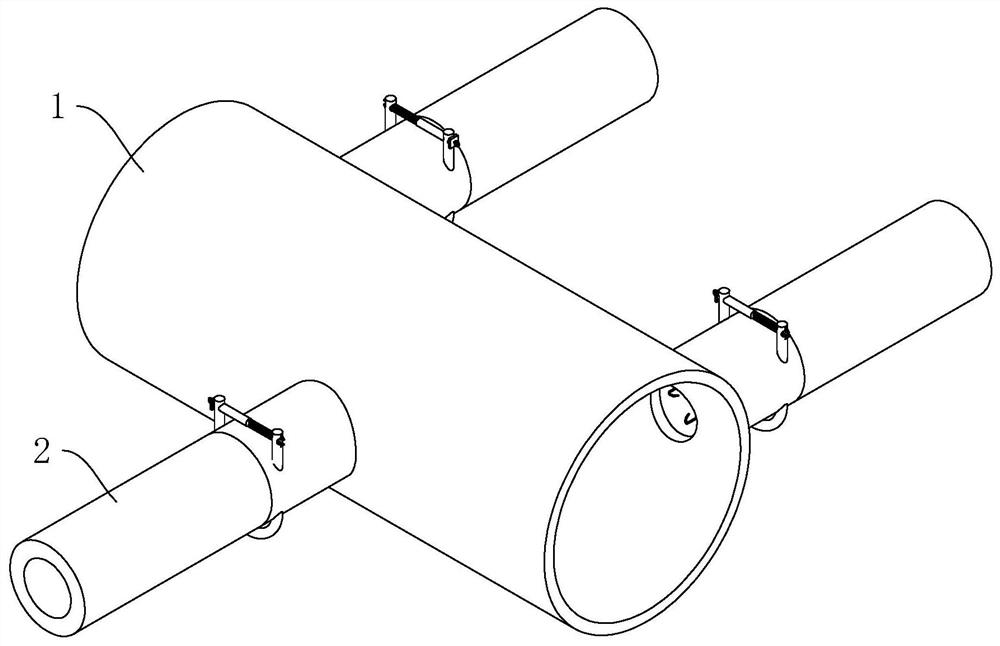
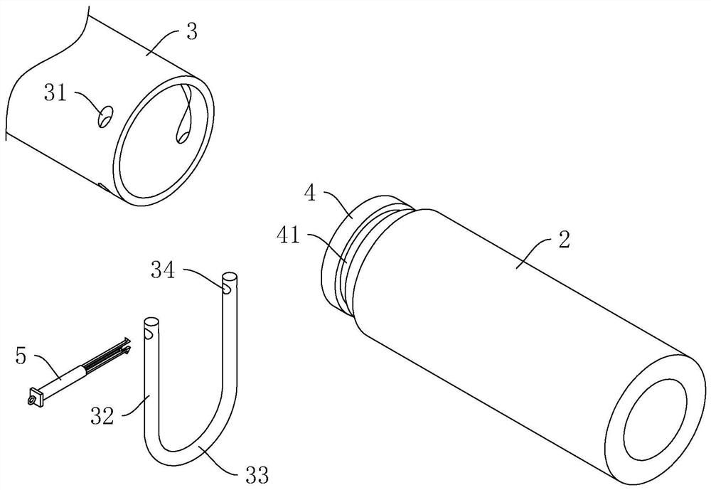
[0040] Embodiment 1: as figure 1 , figure 2 As shown, a municipal pipe network layout structure includes a main pipe 1 and a branch pipe 2 arranged on the side wall of the main pipe 1 . The side wall of the main pipe 1 is provided with a support pipe 3 , and the end of the branch pipe 2 close to the main pipe 1 is provided with a mounting pipe 4 for inserting the support pipe 3 . And in this embodiment, when the installation pipe 4 is inserted into the support pipe 3 , the inner wall of the installation pipe 4 is flush with the inner wall and the outer wall of the support pipe 3 .

[0041] When installing the above-mentioned pipe network, first align the installation pipe 4 at the end of the branch pipe 2 with the support pipe 3 on the side wall of the main pipe 1, and then drive the branch pipe 2 close to the main pipe 1. At this time, the installation pipe 4 slides along the inner wall of the support pipe 3 shift. After the installation pipe 4 is completely inserted into...

Embodiment 2

[0058] Embodiment 2: as Figure 5 As shown, a municipal pipe network layout structure differs from Embodiment 1 in that a sliding sleeve 6 is horizontally slidably connected in the support pipe 3 , and the inner wall of the installation pipe 4 near the end of the support pipe 3 is provided with a barrier against the outer wall of the sliding sleeve 6 . Raised ring 42 .

[0059] Such as Figure 5 As shown, the outer wall of the sliding sleeve 6 is provided with a plurality of elastic ribs 61 , and the end of the elastic ribs 61 away from the sliding sleeve 6 is fixed to the inner wall of the support tube 3 , and the plurality of elastic ribs 61 are evenly distributed along the circumferential direction of the sliding sleeve 6 .

[0060] Such as Figure 5 As shown, the sliding sleeve 6 is close to the main pipe 1 (see figure 1 ) is provided with a plurality of iron hooks 62, and the plurality of iron hooks 62 are evenly distributed along the circumferential direction of the s...

Embodiment 3

[0066] Embodiment 3: a kind of construction method that is used for above-mentioned municipal pipe network layout structure comprises the following steps:

[0067] S1: Take out the branch pipe 2, and make the end with the installation pipe 4 facing the main pipe 1;

[0068] S2: drive the branch pipe 2 to drive the installation pipe 4 to insert the support pipe 3 on the side wall of the main pipe 1;

[0069] S3: After the installation tube 4 is fully inserted into the support tube 3, insert the fixing rod 32 into the fixing hole 31 on one side of the support tube 3, and drive the fixing rod 32 to slide along the fixing hole 31 and the inner wall of the fixing groove 41;

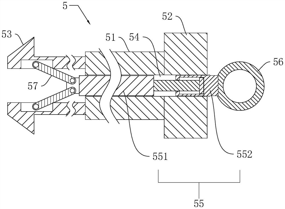
[0070] S4: After the end of the fixing rod 32 passes through the fixing hole 31 on the other side of the support tube 3 , the fixing rod 32 is fixed by the locking part 5 .


PUM


Abstract

The invention discloses a municipal pipe network layout structure, and relates to the field of municipal pipe networks. The municipal pipe network layout structure comprises a main pipe and branch pipes arranged on the side wall of the main pipe. Supporting pipes are arranged on the side wall of the main pipe. Mounting pipes used for being connected with the supporting pipes in an inserted manner are arranged at the ends, close to the main pipe, of the branch pipes. A circle of fixed groove is formed in the outer wall of each mounting pipe. Two fixed holes used for communicating with the corresponding fixed groove are formed in each supporting pipe in a penetrating manner. Fixed rods are slidably connected in the fixed holes in an inserted manner. The two ends of the pair of fixed rods of each supporting pipe are located outside the corresponding mounting pipe, a connecting rod is connected and arranged between one ends of the pair of fixed rods of each supporting pipe, and a locking portion is arranged between the other ends of the pair of fixed rods of each supporting pipe. The locking portions are used for fixing the fixed rods onto the mounting pipes. The municipal pipe network layout structure has the following advantages and effects that through the arrangement of the combined main pipe and branch pipes, traditional welding and fixing are replaced, the branch pipes can be dismounted, and therefore the dredging process of the clogging positions of the joints of the main pipe and the branch pipes is easier and more convenient.

Description

technical field [0001] The invention relates to the field of municipal pipe network, in particular to a municipal pipe network layout structure and a construction method thereof. Background technique [0002] The municipal pipe network project belongs to the pipe network project within the scope of municipal engineering, including power supply underground pipes, rainwater pipes, sewage pipes, water supply pipes, fire pipes, gas pipes, communication pipes, and residential intelligent pipes. [0003] The traditional municipal pipe network usually includes a main pipe and multiple branch pipes connected to the main pipe. Since the branch pipes and the main pipe are usually fixed by welding, when the connection between the branch pipes and the main pipe is clogged, the branch pipes need to be cut off, resulting in The dredging process is very inconvenient and needs to be improved. Contents of the invention [0004] The purpose of the present invention is to provide a municipa...

Claims


Application Information

Patent Timeline
Patent Type & Authority Patents(China)
IPC IPC(8): F16L41/03F16L37/14B08B9/043
CPCB08B9/0436F16L37/144F16L41/03
Inventor 林治星彭紫庭黄伟凯刘新
Owner 深圳星际建筑工程有限公司
Why Eureka
Eureka Blog
Learn More