
Building public flue fume exhaust system and control method thereof

A public flue and smoke exhaust system technology, applied in the field of building public flue, can solve the problems that negative pressure cannot be effectively transmitted, the system exhaust resistance increases, and the balance of fan dynamics is destroyed, so as to solve the problem of poor smoke exhaust, The effect of energy saving of the system and improvement of smoke exhaust capacity

Active Publication Date: 2019-09-24
NINGBO FOTILE KITCHEN WARE CO LTD
View PDF6 Cites 7 Cited by
  • Summary
  • Abstract
  • Description
  • Claims
  • Application Information

AI Technical Summary

Problems solved by technology

However, grease particles are easy to accumulate on the blades of the main fan on the roof, which not only damages the dynamic balance of the fan, resulting in increased noise and vibration, but also requires regular cleaning and maintenance, which is troublesome to maintain
Moreover, the main fan is set on the common exhaust channel, which will increase the exhaust resistance of the system
Especially when the number of floors is greater than 35, the negative pressure generated by the main fan on the top floor cannot be effectively transmitted, and pressure leakage occurs, which has almost zero impact on the smoke exhaust of low-rise users, which instead causes energy waste

Method used


Image

  • Building public flue fume exhaust system and control method thereof
  • Building public flue fume exhaust system and control method thereof
  • Building public flue fume exhaust system and control method thereof

Examples


Embodiment Construction

[0019] The present invention will be further described in detail below in conjunction with the accompanying drawings and embodiments.

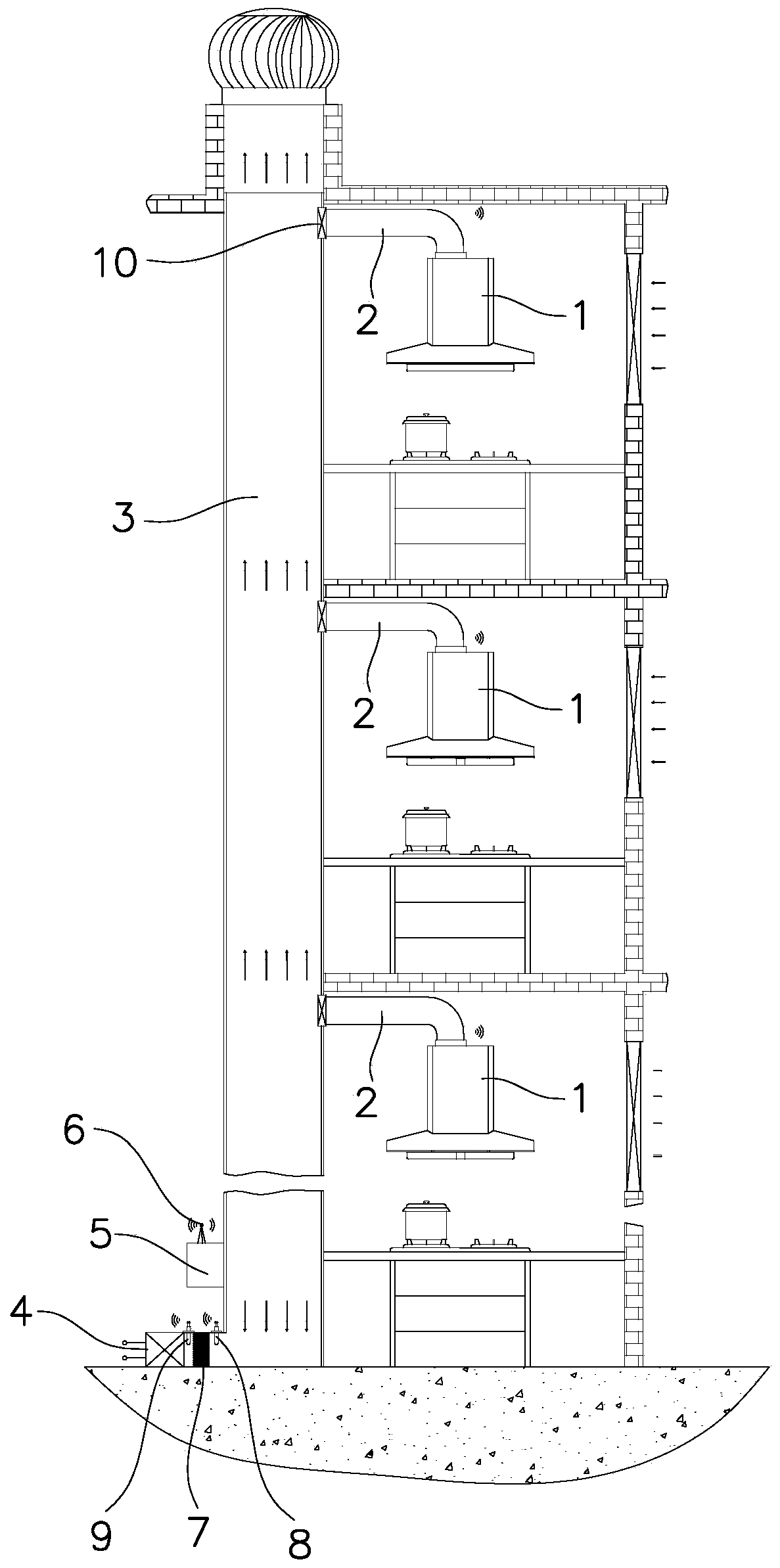
[0020] Such as figure 1 As shown, the smoke exhaust system for the public flue of the building in this embodiment includes range hoods 1 installed on different floors, and the air outlets of each range hood 1 are communicated with the public flue 3 through their respective smoke pipes 2. A fire damper 10 is installed at the outlet of the smoke pipe 2, and the main fan can be installed on the roof, or the main fan can not be installed. This is the prior art, and will not be described in detail.

[0021] An exhaust device 4 is installed at the bottom of the common flue 3, and the exhaust device 4 can draw the fume gas in the common flue 3 outwards as required. At the bottom of the public flue 3, there is a lower air outlet connected to the air inlet of the exhaust device 4. In order to prevent the unpurified oil fumes from being discharged from...


PUM


Abstract

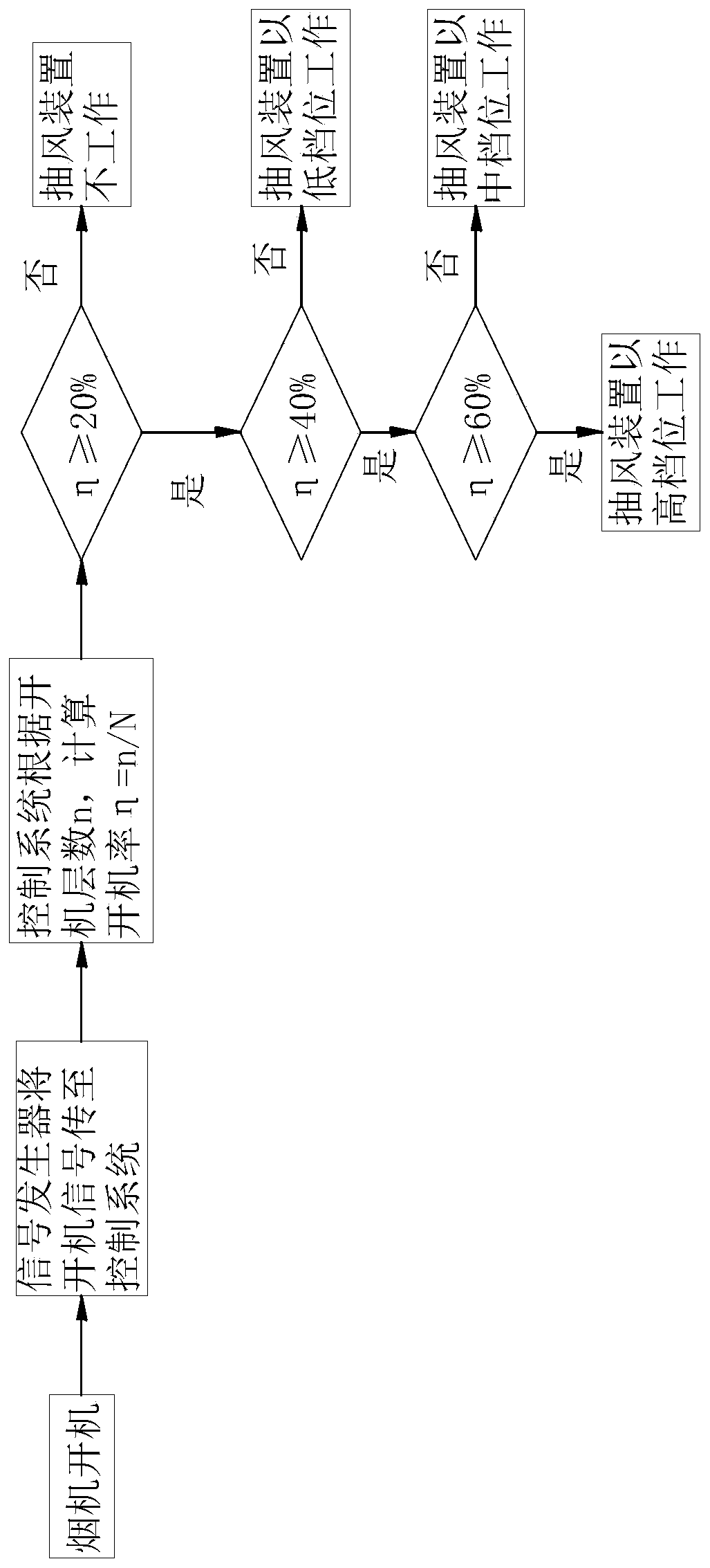
A building public flue fume exhaust system comprises range hoods which are installed on different floors. An air outlet of each range hood communicates with a public flue through a corresponding fume pipe of the range hood. The building public flue fume exhaust system is characterized in that an air suction device which can outwards suck the gas in the flue is installed at the bottom of the public flue. The building public flue fume exhaust system further comprises a control system which can correspondingly control the air suction device according to the value of the starting ratio. The building public flue fume exhaust system has the advantages that the building public flue fume exhaust system can exhaust cooking fumes on the lower layers through the air suction device at the bottom of the flue, the pressure of the bottom of the flue is reduced, and therefore the fume exhaust capacity and the fume exhaust efficiency of the flue are improved, the problems that in the cooking peak time period, the fume exhaust operation of users on the lower layers is not smooth, the fumes return, and the odors spread are solved, and the usage experience of the users is improved. In addition, the control system can correspondingly control the working gear of the air suction device according to the value of the starting ratio, and therefore the intelligent control over the fume exhaust system is achieved, and the system can save more energy.

Description

technical field [0001] The invention relates to a public flue for a building, in particular to a smoke exhaust system for a public flue for a building and a control method thereof. Background technique [0002] At present, there are more and more high-rise residential buildings, and most of the high-rise smoke exhaust uses public flues to exhaust the smoke. The outlets of high-rise public flues are generally set on the top of the floor, and the power provided by the range hood is limited, resulting in unsatisfactory smoke exhaust effects. During peak cooking hours, low-floor oil fumes cannot be exhausted, and even oil fumes in the flue may flow backward. At present, in order to solve the problem of poor smoke exhaust of existing range hoods, people have proposed the concept of "central purification system", which generates power through the main fan placed at the top of the public flue, and cooperates with the range hood fan on the user side to Improve smoke exhaust effect....

Claims


Application Information

Patent Timeline
Patent Type & Authority Applications(China)
IPC IPC(8): F24C15/20E04F17/02
CPCE04F17/02F24C15/2021F24C15/2035
Inventor 于克阳甘从林
Owner NINGBO FOTILE KITCHEN WARE CO LTD
Learn More