Novel test loading device based on lever principle

A technology of loading device and lever principle, applied in measuring devices, instruments, scientific instruments, etc., can solve problems such as failure to obtain test reinforcement effects, and achieve the effects of simple structure, convenient experimental operation and wide application range

Inactive Publication Date: 2019-09-24
DALIAN UNIV OF TECH
View PDF4 Cites 4 Cited by
  • Summary
  • Abstract
  • Description
  • Claims
  • Application Information

AI Technical Summary

Problems solved by technology

If a testing machine or a jack is used for loading, the mid-span loading point is fixed under the condition of holding load, which suppresses the occurrence of S

Method used


Image

  • Novel test loading device based on lever principle
  • Novel test loading device based on lever principle
  • Novel test loading device based on lever principle

Examples


Embodiment 1

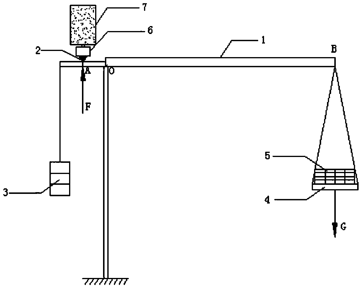
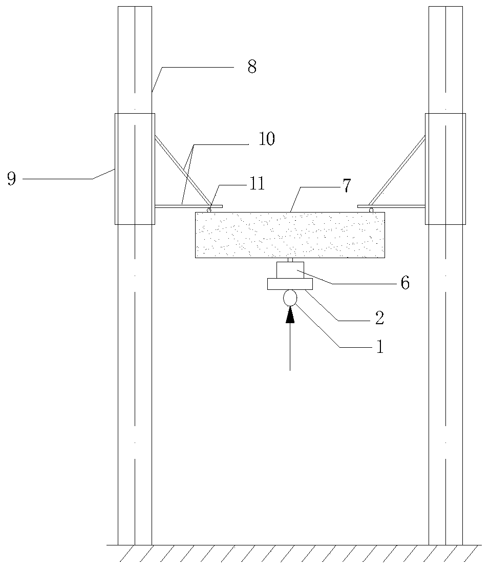
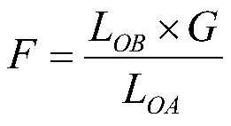
[0020] Such as Figure 1-2 As shown, this embodiment provides a new type of test loading device based on the principle of leverage, including a threaded rod 8 directly anchored in the ground, and a steel casing 9 anchored to the threaded rod 8 through a nut. The steel bracket 10 is two thin steel plates welded to the steel casing 9 . A force sensor 6 is arranged under the test beam 7, and a rotating shaft 2 is arranged under the force sensor to be connected with the lever 1, and the rotating shaft can rotate freely. A balance object 3 is suspended from one end of the lever, and a bearing plate 4 is suspended from the other end, on which a loading object 5 is placed. exist figure 1 A heavy object G is applied to the bearing plate at the position of point B, because the fulcrum O can rotate, then there will be an upward force F applied to the test beam at point A. According to the calculation of the principle of leverage, the force F can be obtained. The mid-span load borne ...

Embodiment 2

[0028] This embodiment provides a method for embedding a shape memory alloy wire at the upper end of a test beam, and the specific steps are:

[0029] 100 Grooving: first loosen the surface of the local cracks of the test beam or clean up the defective parts, and then chisel off a certain thickness of the original concrete protective layer in the local cracked area of ​​the test beam to realize slotting within the depth of the concrete protective layer , the shape of the groove is a dog bone shape, and finally clean up the sundries that have been opened in the groove, and wipe the inner wall of the groove with alcohol;

[0030] 200 tensile alloys: first, install the shape memory alloy on the stretching system, which includes tensioning equipment and sensor data acquisition equipment; adjust the position of the shape memory alloy to ensure that the jack rod of the tensioning equipment and the shape memory alloy The center of the wire is on the same horizontal line, and then the...


PUM


Abstract

The invention discloses a novel test loading device based on the lever principle. According to the novel test loading device, a counterweight is suspended at one end of a steel plate; the other end of the steel plate is connected with one end of a steel tube; a bearing plate is suspended at the other end of the steel tube; and a loading object is arranged on the bearing plate. A notch a is opened in the upper surface of the steel plate; the bottom of a rotating shaft is connected with the notch a in a rotating manner; and a force sensor is arranged on the top of the rotating shaft. A notch b is formed in the lower surface of the steel plate and is opened in the top of a support column. Two threaded rods are anchored on the ground; and a steel casing tube sleeves each threaded rod and is screwed on the corresponding threaded rod by a nut. Steel brackets are welded to the inner sides of the steel casing tubes; and support bases for supporting a test beam are arranged at the bottoms of all steel brackets. According to the provided novel test loading device, on the basis of the reverse loading mode and the graded loading mode, the deformation and carrying capacity restoration effects of the reinforced test beam can be observed under the loaded condition due to the rotatability of the lever.

Description

technical field [0001] The invention belongs to the technical field of civil engineering, in particular to a novel test loading device based on the lever principle method. Background technique [0002] At present, the research on the bending performance of test beams at home and abroad generally uses various testing machines and jacks to conduct three-point loading tests or four-point loading tests. However, in order to embed NiTiNb-SMA wires in the cracked test beam and heat and stimulate it to observe the reinforcement effect achieved under the load-bearing state, none of the above loading equipment tests can be realized. The main reason is that the thermal excitation of the SMA wire will generate a restoring force inside it under the load state, which will act on the test beam as a prestress, so that the beam has a tendency to reverse arch. If a testing machine or a jack is used for loading, the mid-span loading point is fixed under the condition of holding load, which s...

Claims


Application Information

Patent Timeline
IPC IPC(8): G01N3/02
CPCG01N3/02
Inventor 潘盛山王丙达胡美玲苏小菊
Owner DALIAN UNIV OF TECH
Why Eureka
Try Eureka