Assembling tool and method for magnetic suspension bearing rotor

A technology of magnetic suspension bearing and assembling tooling, which is applied in the manufacture of stator/rotor body, etc., can solve the problems of scratches, high operation requirements and retention, and achieves simple process, high rotor coaxiality and position accuracy, and convenient removal of parts. Effect

Pending Publication Date: 2019-09-24
TIANJIN TIANGU MECHANICAL MFG
View PDF0 Cites 0 Cited by
  • Summary
  • Abstract
  • Description
  • Claims
  • Application Information

AI Technical Summary

Problems solved by technology

[0003] The rotor includes a sleeve and a plurality of ring-shaped magnetic-conducting sheets, wherein the multiple ring-shaped magnetically-conducting sheets are stacked together and sleeved outside the sleeve; since the parts of the magnetic suspension bearing are all precision parts, the same The requirements for axiality and position accuracy are very high; the rotor as a key component mainly adopts the following installation method: first heat the magnetic guide sheet, and then set multiple magnetic guide sheets on the casing in turn; after the magnetic guide sheet is cooled, It will be tightly stuck on the casing; and the above-mentioned heating and assembly steps are cumbersome, require high operation, and are prone to assembly failure
In addition, after the assembly is completed, the rotor is generally ejected from the main body of the tool by the top piece. During this process, due to the tight combination of the rotor and the inner wall of the main body of the tool, sometimes it is difficult to remove the main shaft of the rotor and the magnetic guide sheet at the same time, or even Stuck, scratched, etc.

Method used


Image

  • Assembling tool and method for magnetic suspension bearing rotor
  • Assembling tool and method for magnetic suspension bearing rotor
  • Assembling tool and method for magnetic suspension bearing rotor

Examples


Embodiment Construction

[0038] In order to further understand the invention content, characteristics and effects of the present invention, the following examples are given, and detailed descriptions are as follows in conjunction with the accompanying drawings:

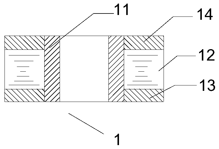
[0039] Such as figure 1 As shown, the rotor 1 to be assembled in the present invention includes: a sleeve 11 and a plurality of annular magnetic conductive sheets 12, and a plurality of annular magnetic conductive sheets 12 are stacked together and sleeved outside the sleeve 11; A first annular baffle 13 and a second annular baffle 14 at both ends of the pipe 11 , wherein a plurality of annular magnetic conductive sheets 12 are sandwiched between the first annular baffle 13 and the second annular baffle 14 .

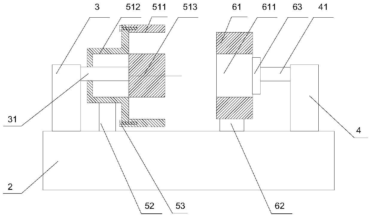
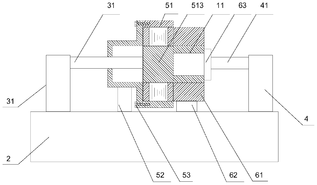
[0040] Such as Figure 2 to Figure 6 As shown, the present invention discloses an assembly tool for the magnetic suspension bearing rotor 1 for the rotor 1 of this structure. A rotor assembly structure 5 is connected; the cylinder two...


PUM


Abstract

The invention belongs to the technical field of magnetic suspension bearings, and particularly discloses an assembling tool and method for a magnetic suspension bearing rotor. The assembling tool comprises a support seat, a first oil cylinder and a second oil cylinder. The first oil cylinder is connected with a rotor assembly structure, and the second oil cylinder is connected with a sleeve pushing structure. The rotor assembly structure comprises a positioning sleeve used for assembling a rotor. A positioning cylinder which is the same as the sleeve in shape and size is arranged at the axis of the positioning sleeve. A first telescopic rod of the first oil cylinder is fixed with the positioning cylinder through a small-diameter part. The sleeve pushing structure comprises a cylindrical sleeve fixing part for pushing the sleeve to a large-diameter part, and a fixing hole matched with the sleeve in shape is formed in the axis of the sleeve fixing part. A push block capable of moving in the axial direction of the fixing hole is arranged at the outer side of the sleeve fixing part; and the push block is fixedly connected with a second telescopic rod on the second oil cylinder. There is no need of heating for rotor assembly, the process is simple and convenient, the coaxiality and the position precision of an installed rotor are high, and the stripping is convenient.

Description

technical field [0001] The invention relates to the technical field of magnetic suspension bearings, in particular to an assembly tool and an assembly method for a magnetic suspension bearing rotor. Background technique [0002] Magnetic suspension bearings use magnetic force to suspend the rotor in the air, so that there is no mechanical contact between the rotor and the stator. Compared with traditional sliding bearings or rolling bearings, it has high speed, high precision, low power consumption, no mechanical contact, no lubrication, etc. advantage. With the continuous improvement of magnetic suspension bearings, it has been widely used in many fields, such as high-speed centrifugal compressors, steam turbine engines, ultra-high-speed machining machine tool spindles, etc. [0003] The rotor includes a sleeve and a plurality of ring-shaped magnetic-conducting sheets, wherein the multiple ring-shaped magnetically-conducting sheets are stacked together and sleeved outside ...

Claims


Application Information

Patent Timeline
IPC IPC(8): H02K15/02
CPCH02K15/02
Inventor 马陕珊徐云胜
Owner TIANJIN TIANGU MECHANICAL MFG
Why Eureka
Try Eureka