Cigarette heating device

A heating device and cigarette technology, applied in tobacco, pipe, application, etc., can solve the problems of inability to guarantee air and smoke storage, inability to achieve better heat insulation effect, poor user experience, etc., to improve user experience, The effect of reducing heat transfer and reducing contact area

Inactive Publication Date: 2019-09-27
CHINA TOBACCO GUANGDONG IND
View PDF6 Cites 5 Cited by
  • Summary
  • Abstract
  • Description
  • Claims
  • Application Information

AI Technical Summary

Problems solved by technology

The heating and baking of cigarettes requires sufficient air. There are two main air path settings for existing cigarette heating devices: one is that the air enters through the gap formed between the cigarette and the heating cavity, and the smoke is released through the cigarette. , this method cannot guarantee sufficient air and smoke storage, and the looseness of cigarettes in the heating chamber affects the quality of the suction; the second is that the air circuit is designed between the inner wall and the outer wall of the heating chamber, and the air is replenished through a pipe near the mouth end. The space between the inner and outer walls of the side enters the bottom of the cavity, and then enters the cigarette through the end of the shredded tobacco. This method has a long gas path and a complicated structure, which cannot achieve a good heat insulation effect and is easy to cause troublesome cleaning. poor user experience

Method used


Image

  • Cigarette heating device
  • Cigarette heating device
  • Cigarette heating device

Examples


Embodiment 1

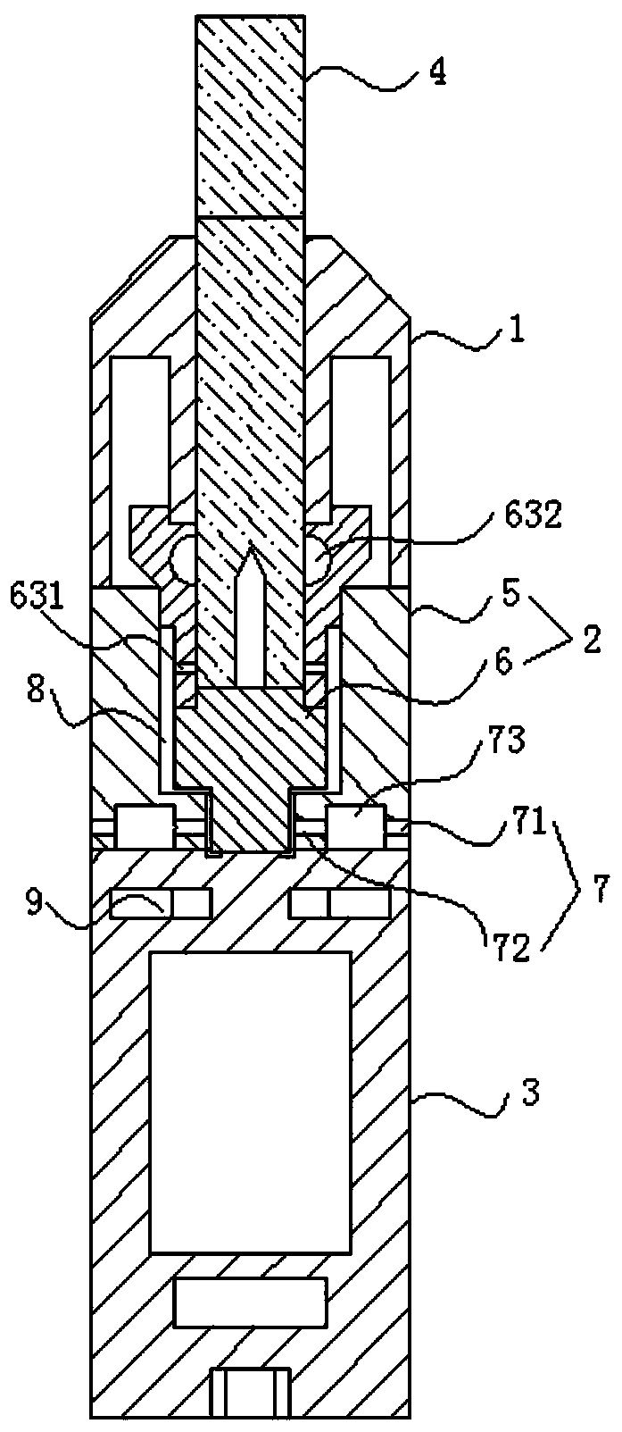
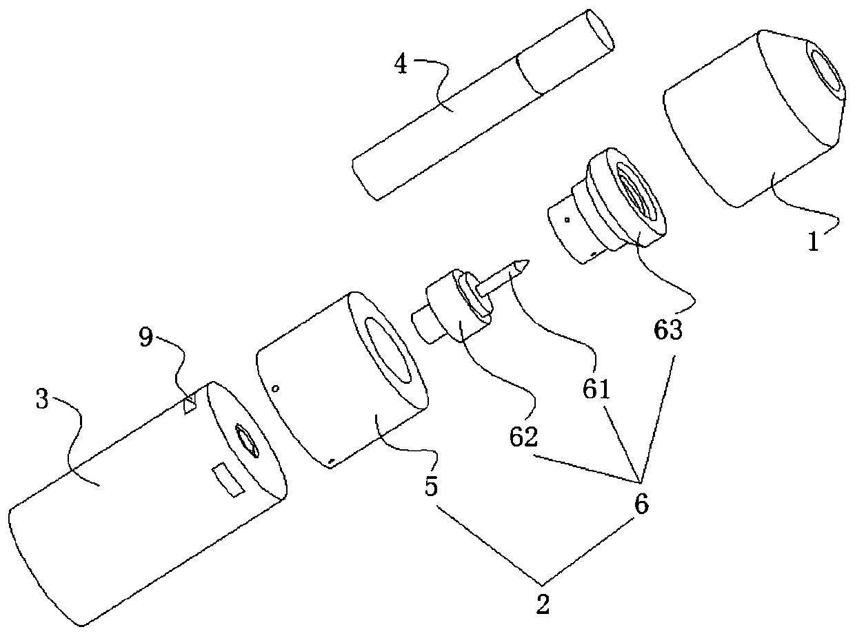
[0026] Such as Figure 1-2 As shown, this embodiment provides a cigarette heating device, which includes a cigarette holder 1, a heating chamber 2 and a base 3 connected in sequence, the top of the heating chamber 2 communicates with the cigarette holder 1, the heating chamber 2 is connected with a power supply device, and the power supply device is set on base 3. Specifically, the power supply device includes a rechargeable battery connected in series, a power adapter and a charging interface, the charging interface is a micro USB interface, and the charging interface can be arranged on the bottom surface of the base 3 .

[0027] Wherein, the heating chamber 2 includes a casing 5 and a heating assembly 6 for heating and roasting the cigarettes 4, and the heating assembly 6 is electrically connected with a power supply device.

[0028] Specifically, as Figure 4 As shown, the housing 5 is a hollow structure, which is arranged around the outside of the heating component 6, le...

Embodiment 2

[0034] Such as Figure 5 As shown, this embodiment also provides a cigarette heating device. The structural principle is similar to that of Embodiment 1. The channel 7 directly connects the air gap 8 inside the heating chamber 2 with the external environment, and is used for air to enter and exit the heating chamber 2 .


PUM


Abstract

The invention relates to the field of electrically heated tobacco devices, in particular to a cigarette heating device. The cigarette heating device comprises a cigarette holder, a heating cavity and a base which are connected in sequence, the top end of the heating cavity communicates with the cigarette holder, the heating cavity is connected with a power supply device, and the power supply device is disposed at the base. The heating cavity comprises a shell and a heating assembly for heating and baking cigarettes, the heating assembly is electrically connected to the power supply device, the shell surrounds the outer side of the heating assembly, and the two ends of the shell are separately connected with the cigarette holder and the base; an air passage is arranged at the bottom end of the shell, and the heating cavity communicates with the external environment the air passage for air to enter and exit the heating cavity. The air enters and exits from the bottom end of the heating cavity of the cigarette heating device, the air circuit path is short, sufficient air reserves and flue gas reserves can be reserved, and an effective heat insulation structure is further arranged for heat insulation of the cigarette heating device.

Description

technical field [0001] The invention relates to the field of electric heating tobacco devices, and more specifically, relates to a cigarette heating device. Background technique [0002] The combustion temperature of traditional cigarettes is very high, about 900°C. Such a high temperature will decompose and release many harmful components. The smoke produced will affect the smoker on the one hand, and on the other hand, the surrounding people. Such as harmful to health, bad smell. Different from the traditional way of burning and smoking with open flame, because there is no open flame to burn, the smoking method of using non-burning heating device to bake cigarettes avoids the process of high-temperature cracking and releasing harmful components, and the generation of harmful substances in the smoke is much lower than that of cigarettes. Harmful substances produced by traditional cigarettes after burning. [0003] Cigarette heating device is an electronic device that heat...

Claims


Application Information

Patent Timeline
Patent Type & Authority Applications(China)
IPC IPC(8): A24F13/02A24F13/08
CPCA24F13/02A24F13/08A24F40/20A24F40/46A24F40/485A24F40/40A24F13/22
Inventor 赵瑞峰胡静李峰吴桂周张延军刘义波叶荣飞
Owner CHINA TOBACCO GUANGDONG IND
Why Eureka
Try Eureka