Continuous fiber reinforced composite wire manufacturing equipment

A technology for reinforced composite materials and continuous fibers, which is applied in the field of continuous fiber reinforced composite material wire manufacturing equipment, can solve the problems of heat loss, long conveying pipeline path, complicated nozzle structure, etc., so as to reduce the design difficulty and optimize the overall structure and state easy-to-manage effects

Active Publication Date: 2021-06-11
HEBEI UNIVERSITY OF SCIENCE AND TECHNOLOGY
View PDF7 Cites 0 Cited by
  • Summary
  • Abstract
  • Description
  • Claims
  • Application Information

AI Technical Summary

Problems solved by technology

[0003] Most of the materials used in 3D printing technology are single materials, and the preparation method of composite filaments is not yet mature
Therefore, in order to meet higher usage requirements and overcome the shortcomings of insufficient comprehensive mechanical properties of existing 3D printing filaments, continuous fiber composite filament manufacturing equipment has emerged as the times require.
However, in the existing continuous fiber composite filament manufacturing equipment, the heating mechanism and the nozzle are often connected by a conveying pipe to convey the molten matrix. In order to realize the effective compounding of the molten matrix and the continuous fiber, the nozzle structure is relatively complicated. , due to the long path of the pipeline and heat loss, etc., it is often necessary to install a heating device at the position of the nozzle, which makes the design of the nozzle difficult and is not conducive to optimizing the overall structure of the equipment

Method used


Image

  • Continuous fiber reinforced composite wire manufacturing equipment
  • Continuous fiber reinforced composite wire manufacturing equipment
  • Continuous fiber reinforced composite wire manufacturing equipment

Examples


Embodiment Construction

[0064] In order to make the technical problems, technical solutions and beneficial effects to be solved by the present invention clearer, the present invention will be further described in detail below in conjunction with the accompanying drawings and embodiments. It should be understood that the specific embodiments described here are only used to explain the present invention, not to limit the present invention.

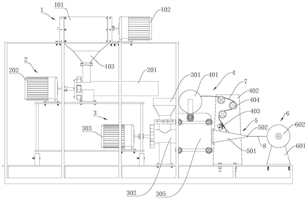
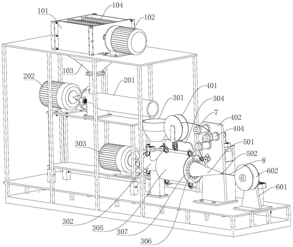
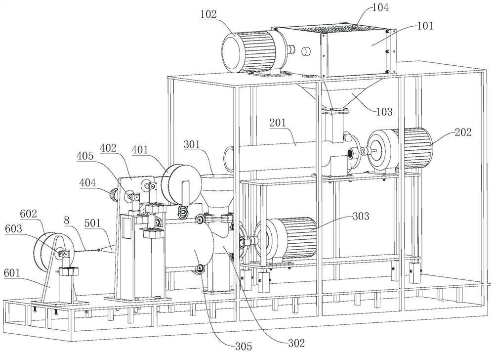
[0065] Please also refer to Figure 1 to Figure 4 , Figure 10 and Figure 11 , the continuous fiber-reinforced composite filament manufacturing equipment provided by the present invention will now be described. The continuous fiber reinforced composite filament manufacturing equipment includes a crushing mechanism 1, a conveying mechanism 2, a melting mechanism 3, a wire feeding mechanism 4, an extrusion mechanism 5 and a wire receiving mechanism 6; the conveying mechanism 2 is connected to the crushing mechanism 1, It is used to transport crushed raw materials...


PUM


Abstract

The invention provides continuous fiber reinforced composite wire manufacturing equipment. The continuous fiber reinforced composite wire manufacturing equipment comprises a crushing mechanism, a conveying mechanism, a melting mechanism, a wire feeding mechanism, an extruding mechanism and a wire collecting mechanism; the conveying mechanism is in butt joint with the crushing mechanism, and is used for conveying crushed raw materials; the melting mechanism is in butt joint with the conveying mechanism, and is used for heating the crushed raw materials to form molten basal bodies; the wire feeding mechanism is used for conveying continuous fibers; the extruding mechanism is provided with a first shell in the shape of a conical cylinder; a large end of the first shell is directly in butt joint with an outlet of the melting mechanism, and a nozzle is arranged at a small end; a fiber inlet for enabling the continuous fibers to enter is formed in the side wall of the first shell; and the wire collecting mechanism is used for collecting continuous fiber reinforced composite wires sprayed out by the nozzle. According to the continuous fiber reinforced composite wire manufacturing equipment, the design difficulty of the nozzle is reduced, and meanwhile, optimization of the overall structure of the equipment is facilitated.

Description

technical field [0001] The invention belongs to the technical field of production of continuous fiber-reinforced composite materials, and in particular relates to a continuous fiber-reinforced composite material filament manufacturing equipment. Background technique [0002] Continuous fiber composite filament manufacturing is a cross-research direction in the field of composite material forming and additive manufacturing. It is mainly used in the design and manufacture of composite aircraft structures, which will greatly improve the manufacturing efficiency and comprehensive performance of aircraft. At the same time, it is applied to new energy vehicles and other frontiers. It has important research significance and broad application prospects, and has become a research hotspot at home and abroad. [0003] Most of the materials used in 3D printing technology are single materials, and the preparation method of composite filaments is still immature. Compared with traditional...

Claims


Application Information

Patent Timeline
Patent Type & Authority Applications(China)
IPC IPC(8): B29C48/05B29C48/154B29C48/68B29B15/14
CPCB29C48/05B29C48/154B29C48/68B29B15/14Y02W30/62
Inventor 杨立宁杨光姚川黄华蒙
Owner HEBEI UNIVERSITY OF SCIENCE AND TECHNOLOGY
Why Eureka
Try Eureka