Craniocerebral surgery fixation device and method of use thereof
A fixation device, a technique for craniocerebral surgery, which is used in operations, operating tables, and stereotaxic surgical instruments, etc., can solve problems such as inconvenient operation, difficulty in achieving craniocerebral fixation, and patient injury, so as to reduce damage and improve the effect of craniocerebral fixation. Effect
- Summary
- Abstract
- Description
- Claims
- Application Information
AI Technical Summary
Problems solved by technology
Method used
Image
Examples
Embodiment 1
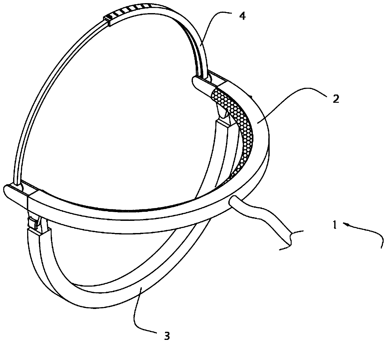
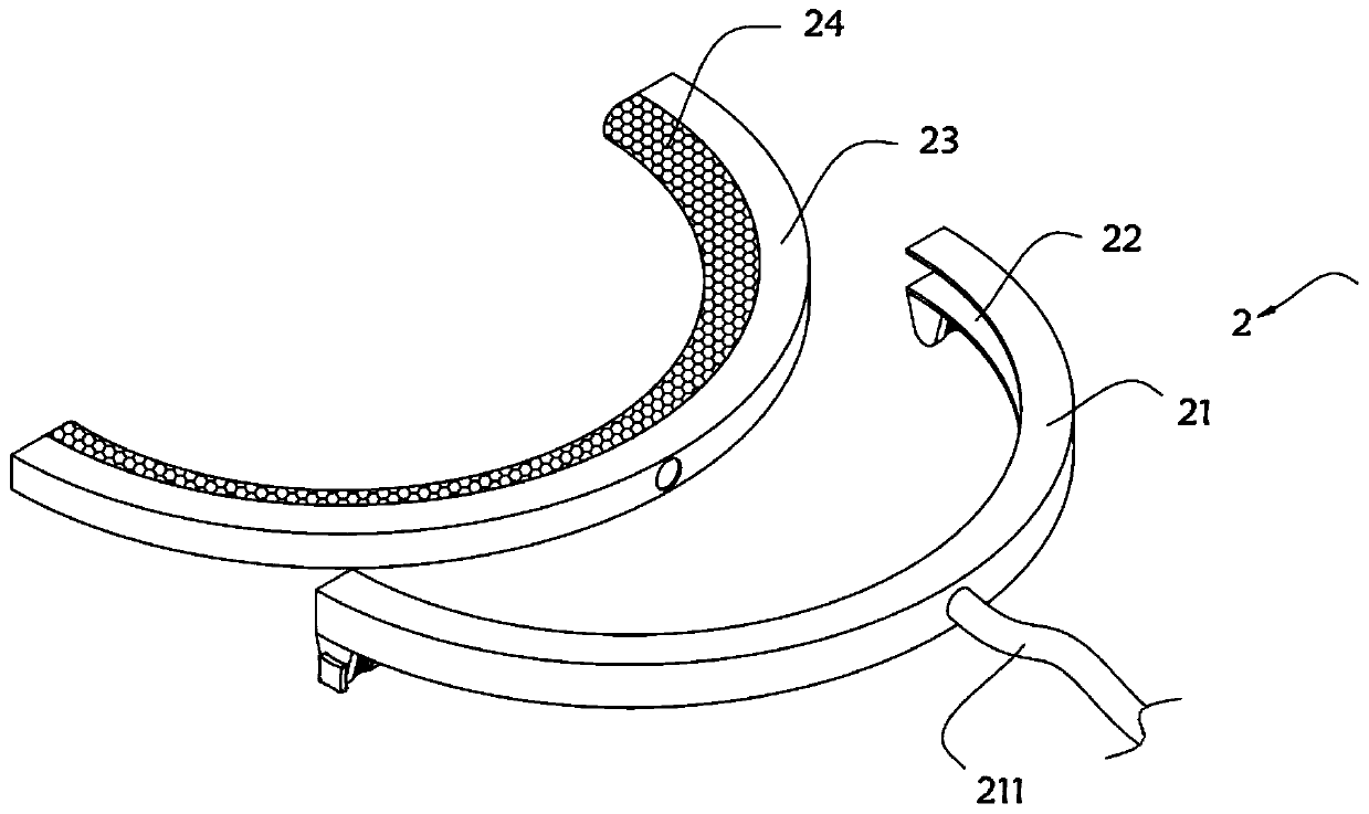
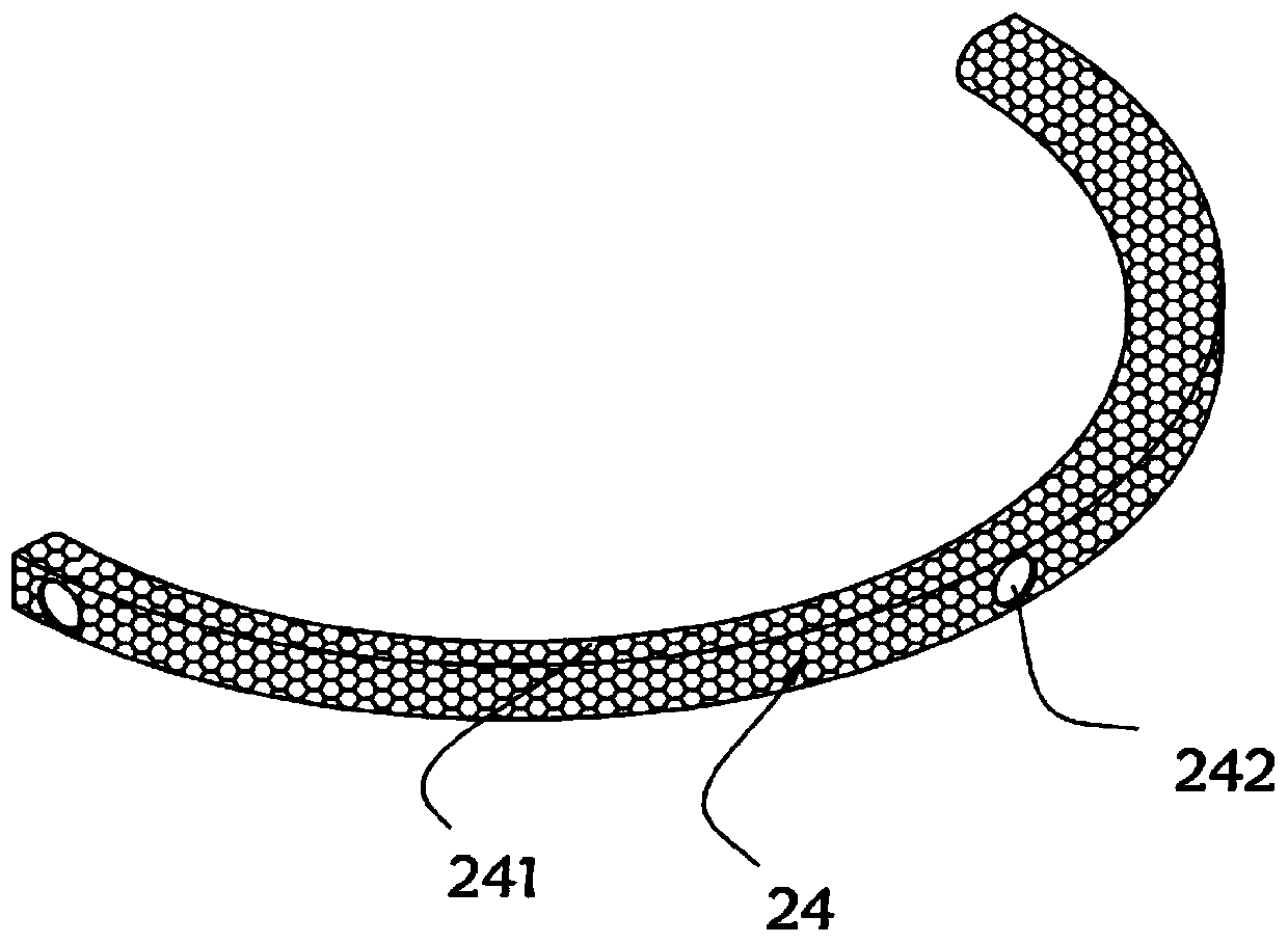
[0040] On the one hand, the present invention provides a craniocerebral surgery fixation device, such as Figure 1-Figure 6 As shown, the device body 1 is included, and the device body 1 includes a cranium clamping mechanism 2 for clamping the cranium, a cranium supporting plate 3 installed at the bottom of the cranium clamping mechanism 2 and a cranium clamping mechanism installed on the cranium clamping mechanism 2. Brain clamping mechanism 4 at the top. The cranium clamping mechanism 2 includes a cranium splint 21. An inner groove 22 is opened inside the splint 21. A water storage plate 23 is clamped on the inner wall of the inner groove 22. The water storage plate 23 The inner wall is equipped with a compression strip 24, and the center of the outer wall of the water storage plate 23 is provided with a connecting hole 231. The inner wall of the water storage plate 23 is provided with a plurality of inner holes 232, and a water outlet mechanism 233 is installed in the inner ...
Embodiment 2
[0049] As the second embodiment of the present invention, in order to facilitate the support of the brain, the inventors made improvements to the brain support plate 3, as a preferred embodiment, such as Figure 7-Figure 9 As shown, the bottoms of the two ends of the cranial splint 21 are respectively equipped with adjusting parts 25, and the tops of the two ends of the cranial supporting plate 3 are respectively provided with connecting seats 31, and the connecting seats 31 are provided with rotating holes 32. The adjusting parts 25 include a pair of mounting A protruding inner ring 252 is installed on the inner wall of the seat 251 , and the inner ring 252 is rotatably connected to the rotating hole 32 .
[0050] In this embodiment, the inner wall of the inner ring 252 is engraved with an internal thread 253, and the outer wall of the mounting seat 251 located outside the brain splint 21 is provided with a thread groove 254, so that the screw rod 255 can be screwed in from th...
Embodiment 3
[0055] Such as Figure 10-Figure 13 As shown, a pair of connecting plates 26 are respectively provided at both ends of the cranial splint 21, and a rotating shaft 27 is installed between the two connecting plates 26, and a rotating cylinder 28 connected to the rotating shaft 27 is sleeved on the rotating shaft 27, and the tightening mechanism 4 includes a The binding strip 41 on one of the rotating cylinders 28, the binding mechanism 4 also includes a clamping strip 42 installed on the other rotating cylinder 28, the binding strip 41 is made of tough plastic material, and a limit block is arranged on the top of one end of the binding strip 41 43. The limiting block 43 is provided with a base 431, a limiting groove 432 and an inserting block 433 sequentially from bottom to bottom. The clamping strip 42 is also made of tough plastic material, and the clamping strip 42 is provided with an adjustment for sliding cooperation with the binding strip 41. The slot 421 and the top of th...
PUM
 Abstract
Description
Claims
Application Information
 - R&D
- Intellectual Property
- Life Sciences
- Materials
- Tech Scout
- Unparalleled Data Quality
- Higher Quality Content
- 60% Fewer Hallucinations
Browse by: Latest US Patents, China's latest patents, Technical Efficacy Thesaurus, Application Domain, Technology Topic, Popular Technical Reports.
© 2025 PatSnap. All rights reserved.Legal|Privacy policy|Modern Slavery Act Transparency Statement|Sitemap|About US| Contact US: help@patsnap.com


