
Hydraulic control valve body outer surface automatic spraying device

A technology of automatic spraying and hydraulic control valve, which is applied to the surface coating device, spraying device, coating and other directions. The effect of spraying quality, improving paint accumulation, and improving smoothing effect

Active Publication Date: 2019-09-27
嘉兴智旭信息科技有限公司
View PDF17 Cites 3 Cited by
  • Summary
  • Abstract
  • Description
  • Claims
  • Application Information

AI Technical Summary

Problems solved by technology

However, the current automatic spraying device for the outer surface of the hydraulic control valve has the following disadvantages: 1. Since the outer surface of the hydraulic control valve is mostly curved, and the distance from the nozzle to the outer surface of the hydraulic control valve is not equal, the spraying is uneven; 2. .The automatic spraying device does not have the function of smoothing, which is easy to cause paint accumulation, which in turn affects the spraying quality of the outer surface of the hydraulic control valve

Method used


Image

  • Hydraulic control valve body outer surface automatic spraying device
  • Hydraulic control valve body outer surface automatic spraying device
  • Hydraulic control valve body outer surface automatic spraying device

Examples


Embodiment Construction

[0026] Embodiments of the present invention will be described below with reference to the drawings. In the process, in order to ensure the clarity and convenience of illustration, we may exaggerate the width of the lines or the size of the constituent elements in the diagram.

[0027] In addition, the following terms are defined based on the functions in the present invention, and may be different according to the user's or operator's intention or practice. Therefore, these terms are defined based on the entire content of this specification.

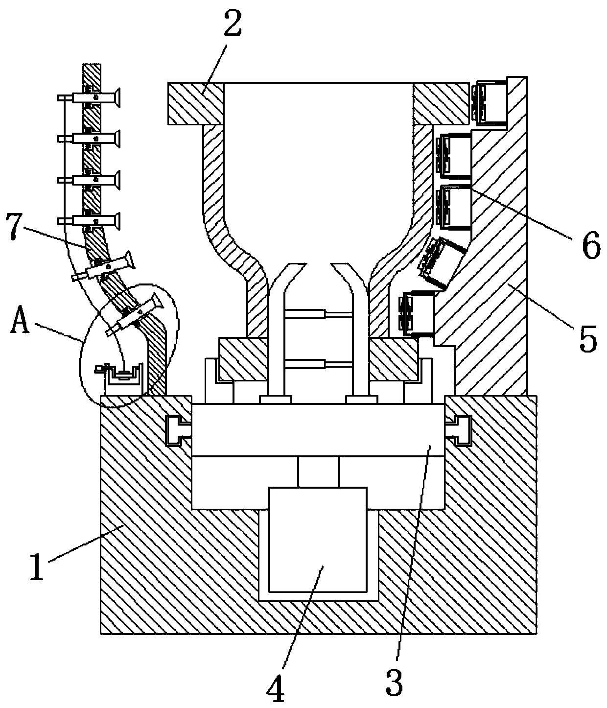
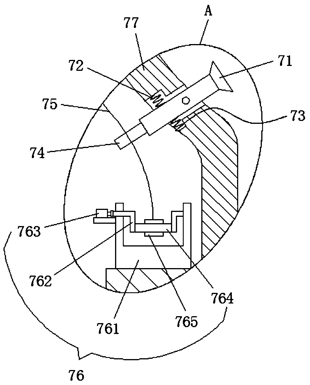
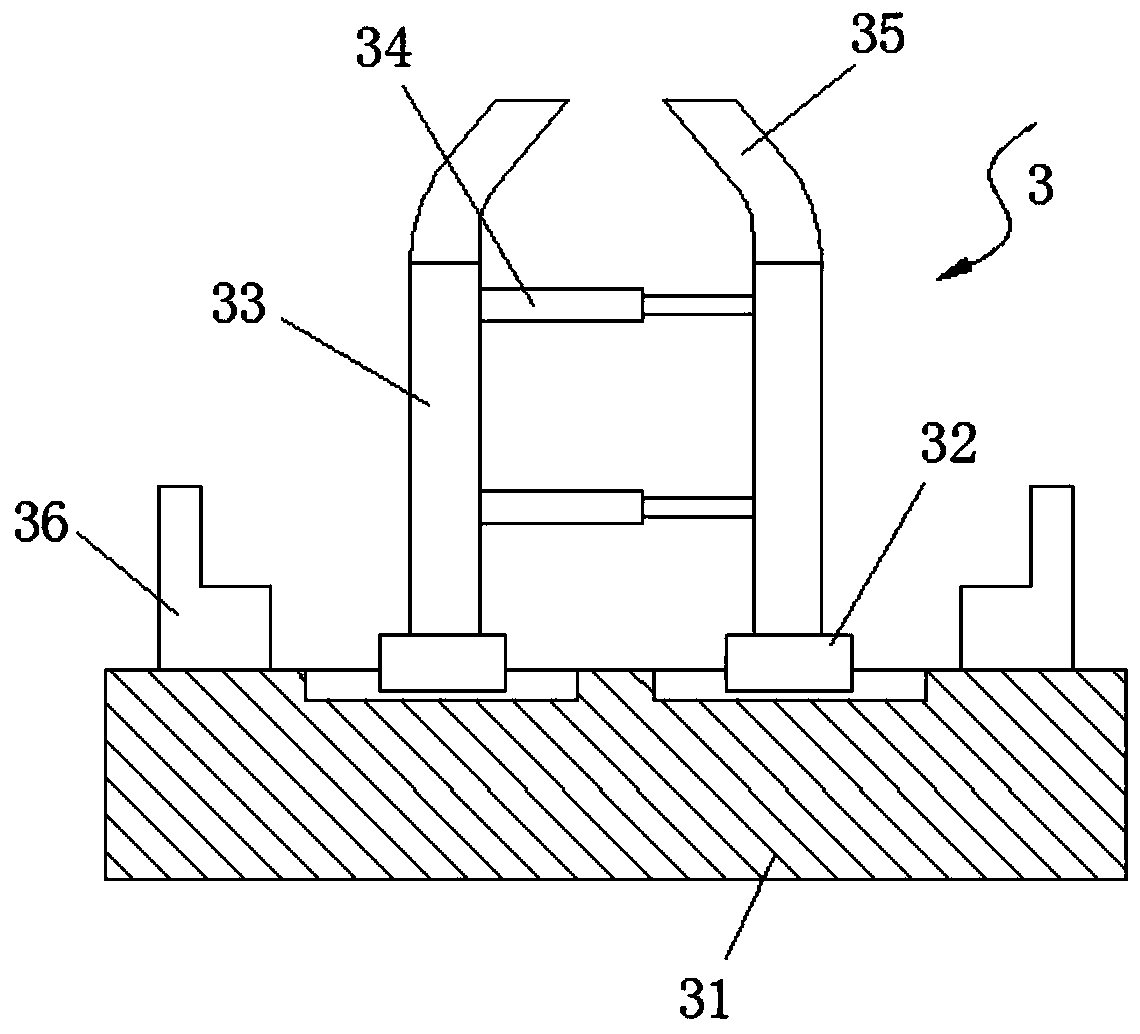
[0028] like Figure 1-4 As shown, an automatic spraying device for the external surface of a hydraulic control valve includes a U-shaped base 1, the top surface of the U-shaped base 1 is slidingly provided with a clamping mechanism 3, and the top surface of the U-shaped base 1 is provided with a motor 4, and the output of the motor 4 The shaft is connected to the bottom surface of the clamping mechanism 3, the periphery of the clamping...


PUM


Abstract

The invention relates to a hydraulic control valve body outer surface automatic spraying device which comprises a U-shaped base, wherein a clamping mechanism is arranged on the top surface of the U-shaped base in a sliding manner; a motor is arranged on the top surface of the U-shaped base; the output shaft of the motor is connected with the bottom surface of the clamping mechanism; a hydraulic control valve body is arranged on the periphery of the clamping mechanism; a spraying mechanism is arranged at the left end of the U-shaped base; a uniform spraying mechanism is arranged at the right end of the U-shaped base through a right side plate; the spraying mechanism comprises a left side plate; mounting holes are uniformly formed in the left side plate from top to bottom; a sprayer is rotatably arranged in the mounting holes and is connected with a paint sprayer through a pipe body; a buffering cavity is formed in the left side plate; an upper spring is arranged between the top surface of the sprayer and the top surface of the buffering cavity; a lower spring is arranged between the bottom surface of the sprayer and the bottom surface of the buffering cavity; and the elastic force of the lower spring is greater than that of the upper spring. The hydraulic control valve body outer surface automatic spraying device is uniform in spraying, improves the paint accumulation phenomenon and ensures the spraying quality of the outer surface of the hydraulic control valve body.

Description

technical field [0001] The invention relates to the technical field of a hydraulic control valve body, in particular to an automatic spraying device for the outer surface of a hydraulic control valve body. Background technique [0002] The hydraulic control valve body is the main part of the valve, which is generally cast or forged, and valve bodies with different pressure levels can be manufactured according to needs. The hydraulic control valve body is used to control the on-off and flow rate of the fluid pipeline. The hydraulic control valve body is generally exposed to the outside and needs to withstand the erosion of the external environment. In order to enhance the anti-corrosion ability of the outer surface of the hydraulic control valve, spraying treatment is required on the outer surface of the hydraulic control valve. [0003] The spraying operation on the external surface of the hydraulic control valve requires the use of an automatic spraying device. However, ...

Claims


Application Information

Patent Timeline
Patent Type & Authority Applications(China)
IPC IPC(8): B05B13/04B05B13/02B05C11/02
CPCB05B13/0228B05B13/0278B05B13/0405B05C11/025
Inventor 郭颂姚维杰张金峰
Owner 嘉兴智旭信息科技有限公司
Learn More