Thin-wall part machining method

A processing method and technology for thin-walled parts, applied in the field of aero-engine manufacturing, can solve the problems of tool or measuring tool interference, disc-type parts end face and measuring tool interference, increasing the difficulty of measuring tool design, etc., to achieve the effect of saving production costs

Active Publication Date: 2019-09-27
CHINA HANGFA GUIZHOU LIYANG AVIATION POWER CO LTD
View PDF7 Cites 2 Cited by
  • Summary
  • Abstract
  • Description
  • Claims
  • Application Information

AI Technical Summary

Problems solved by technology

Since thin-walled parts can only be clamped by supporting, positioning, and clamping to ensure the accuracy of the parts, traditional processing methods require the combination of multiple sets of fixtures to ensure the support, positioning, and compression of the parts.
In addition, it is necessary to measure the depth value of some points at any time during the processing process, such as the depth of the point on the web, but there will be a problem of interference between the end face of the disc part and the measuring tool during the measurement process, which increases the difficulty of measuring tool design
For the pressing structure, the commonly used pressing hook will also cause interference with the tool or measuring tool because its pressing position is on the end surface of the part.

Method used


Image

  • Thin-wall part machining method

Examples


Embodiment Construction

[0020] The technical solution of the present invention will be further described below in conjunction with the accompanying drawings, but the claimed protection scope is not limited to the description.

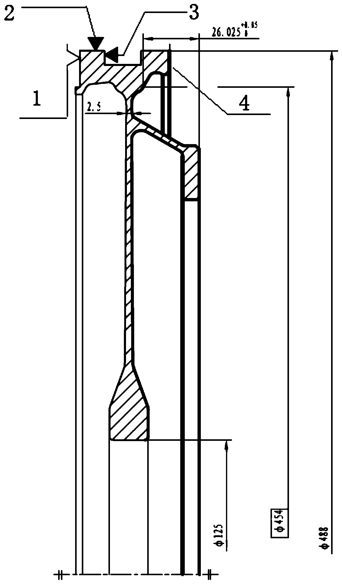
[0021] Such as figure 1 As shown, it is a high-pressure compressor disk part. The compressor disk is a large-span thin-walled disk part. Due to the large structural size of the part, the outer circle size of the part is The size of the inner hole is The thinnest part wall thickness is only 2.5mm. This part belongs to the thin-walled compressor disk part, and it must be clamped by supporting positioning and pressing during processing. Considering the cost factor in the processing, the concave-shaped construction edge is used to ensure that all the turning processing can be completed with one fixture.

[0022] The specific processing method is: reserve 5mm of the radial length of the outer circle at the largest part of the outer circle as the annular machining allowance sid...


PUM


Abstract

The invention discloses a thin-wall part machining method. The method comprises the steps that the allowance is reserved, and specifically, an annular machining allowance edge which is coaxial with a part is reserved along the maximum outer circle position of the diameter of the part; a groove is machined, and specifically, an annular groove coaxial with the part is machined in the annular machining allowance edge; and the part is clamped, specifically, an end surface which is located at the annular machining allowance edge and is perpendicular to the axis direction of the part is used as a supporting side, an outer circumferential surface of the annular machining allowance edge is used as a positioning surface, and an annular surface, perpendicular to the axis direction of the part, in the annular groove is used as a pressing surface of a pressing hook. The thin-wall part machining method avoids that a plurality of clamps are applied to the same part during machining, and reduces the time and production cost caused by a clamp combination, a support positioning and pressing manner is adopted to prevent deformation of the part, and the pressing hook of the part is hidden inside the part and does not interference with the turning and measurement on the depth direction.

Description

technical field [0001] The invention belongs to the field of aero-engine manufacturing, in particular to a processing method for thin-walled disk parts. Background technique [0002] At present, in the manufacturing process of aero-engines, the processing of many thin-walled disk parts is involved. Since the thin-walled parts can only be supported, positioned and clamped to ensure the accuracy of the parts, the traditional processing method requires the combination of multiple sets of fixtures to ensure the support, positioning and compression of the parts. In addition, the depth value of some points needs to be measured at any time during the processing process, such as the depth of the point on the web, but the end face of the disc part will interfere with the measuring tool during the measurement process, which increases the difficulty of measuring tool design. For the pressing structure, the commonly used pressing hook will also cause the problem of interference with th...

Claims


Application Information

Patent Timeline
Patent Type & Authority Applications(China)
IPC IPC(8): B23B1/00
CPCB23B1/00
Inventor 惠畅张玉谭家进李亚初
Owner CHINA HANGFA GUIZHOU LIYANG AVIATION POWER CO LTD
Why Eureka
Try Eureka