Anti-pouring type brake pedal device

A brake pedal and anti-tilt technology, which is applied in the direction of braking action starting devices, foot starting devices, brakes, etc., can solve the problems of unstable deformation of seat body sheet metal, interruption of transmission routes, and impact on safety, and achieve structural Simple, stable power transmission, and occupant protection

Pending Publication Date: 2019-09-27
无锡金尚汽车技术开发有限公司
View PDF0 Cites 0 Cited by
  • Summary
  • Abstract
  • Description
  • Claims
  • Application Information

AI Technical Summary

Problems solved by technology

The traditional anti-tilting pedal assembly is mostly set on the pedal shaft, and is assembled with a split base. When an impact occurs, the pedal base is separated, and the pedal pin falls off along the main seat groove when the pedal base is separated, realizing The transmission route is interrupted. This kind of mechanism is relatively complicated, and the deformation of the seat sheet metal is unstable, which affects safety.

Method used


Image

  • Anti-pouring type brake pedal device
  • Anti-pouring type brake pedal device
  • Anti-pouring type brake pedal device

Examples


Embodiment Construction

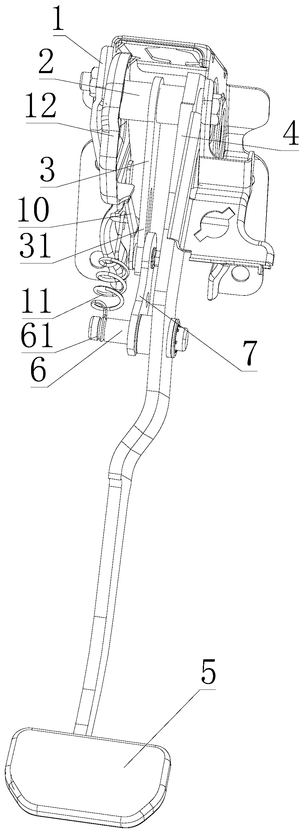
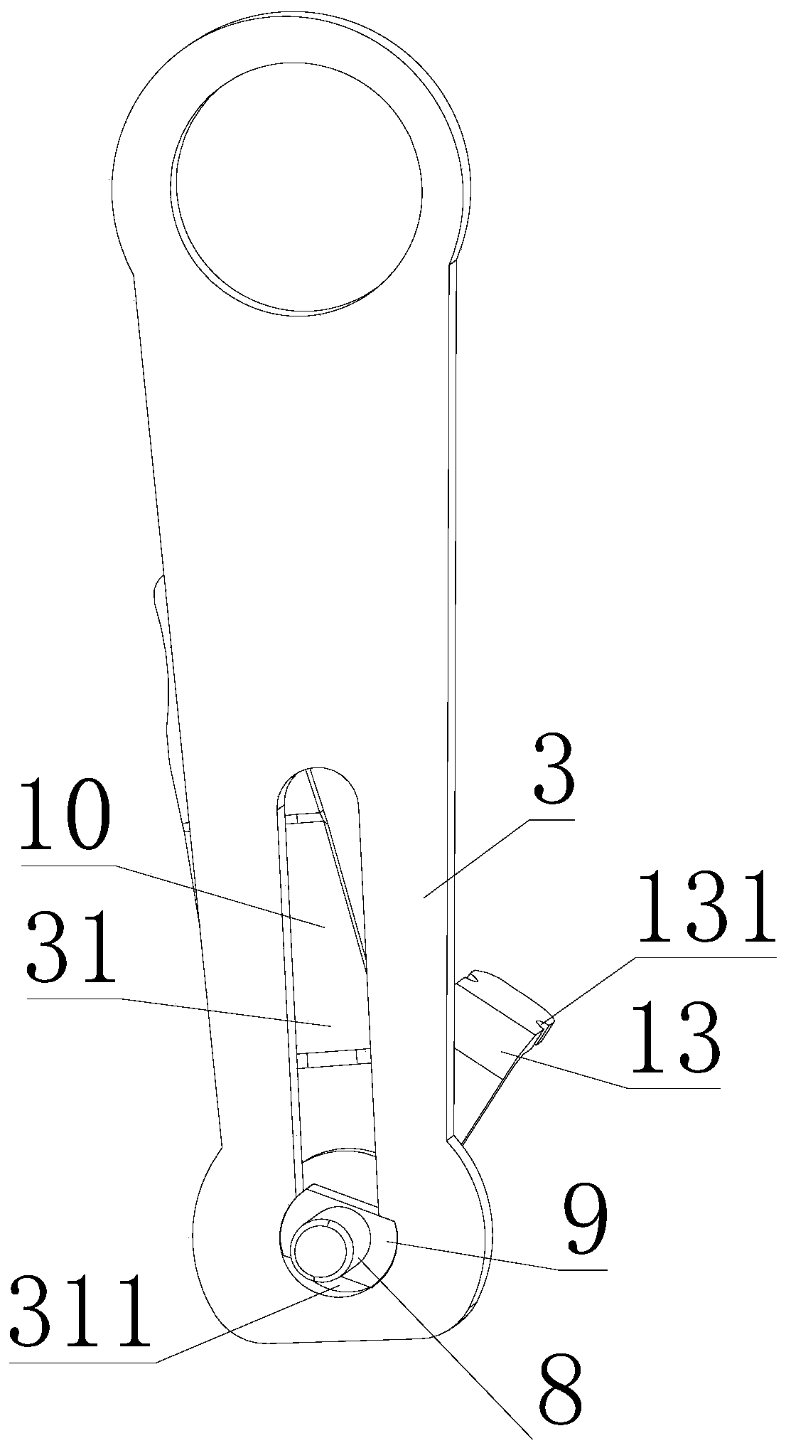
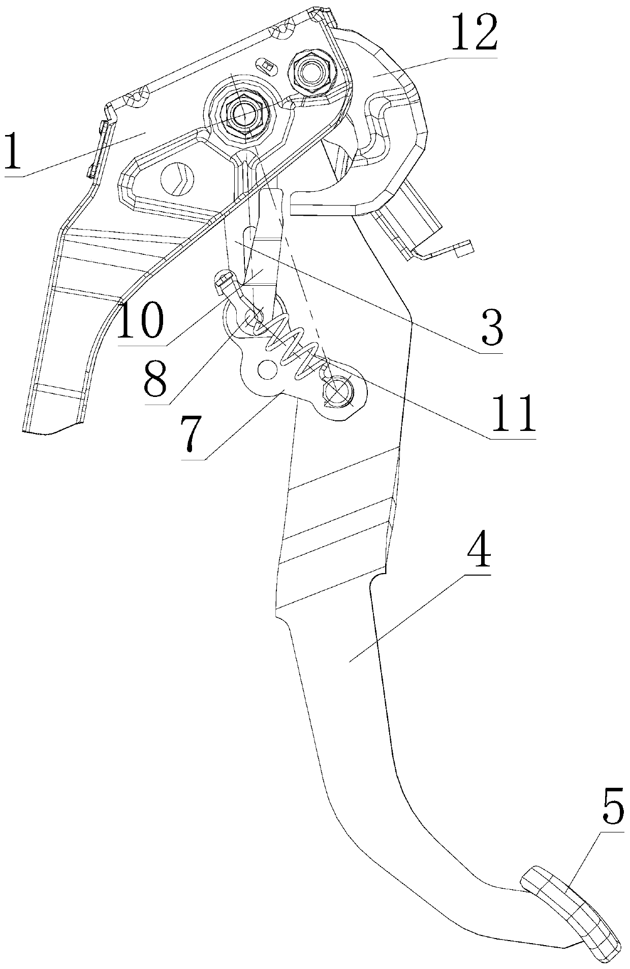
[0022] As shown in the figure, the anti-tilting brake pedal device in this embodiment includes a pedal base 1, on which a connecting shaft 2 is arranged, and a long support arm 3 and a pedal arm are rotatably connected to the connecting shaft 2. 4. There is a pedal 5 at the bottom of the pedal arm 4, and the end of the long arm 3 is provided with a chute 31 in the axial direction. 6. A short arm 7 is set on the rotating shaft 6, and one end of the short arm 7 is connected to a cylindrical pin 8, and the cylindrical pin 8 is provided with a limit block 9 placed in the limit card groove 311. In this embodiment, the limit block 9 is a waist block, the limit block 9 can rotate with the cylindrical pin 8 to move in the chute 31, the end of the cylindrical pin 8 is fixedly connected to the rotating arm 10, the spring 11 is connected between the rotating arm 10 and the rotating shaft 6, and the pedal seat 1 A trigger 12 is also installed on the top, and the trigger 12 is arranged on ...


PUM


Abstract

The invention discloses an anti-pouring brake pedal device. The anti-pouring brake pedal device comprises a pedal seat; a connecting shaft is arranged on the pedal seat; the connecting shaft is rotationally connected with a long supporting arm and a pedal arm; a sliding groove is formed in the end part of the long supporting arm in the axial direction; a limiting clamping groove is formed in the end part of the sliding groove; a rotary shaft is arranged at the end part of the pedal arm; a short supporting arm is arranged on the rotary shaft in a sleeving mode; one end of the short supporting arm is connected with a cylindrical pin; a limiting block arranged in the limiting clamping groove is arranged on the cylindrical pin; the limiting block can rotate along with the cylindrical pin to move in the sliding groove; the end part of the cylindrical pin is fixedly connected with a rotary arm; a spring is connected between the rotary arm and the rotary shaft; the pedal seat is provided with a trigger part; the trigger part is arranged on one side of the rotary arm; and the rotary arm can be pushed to rotate when the trigger part rotates. According to the anti-pouring brake pedal device, a brake pedal power transmission route is integrated on the pedal arm, a stable geometric structure can be realized, the power transmission is stable before triggering, the energy transmission of the pedal arm can be effectively disconnected after triggering, passengers are protected, and the safety performance is high.

Description

technical field [0001] The invention relates to the technical field of automobile brake devices, in particular to an anti-tilting brake pedal device. Background technique [0002] With the continuous improvement of people's living standards, cars have brought a lot of convenience to people's travel. At the same time, with the continuous upgrading of products in the automotive market, the requirements for vehicle collision safety are becoming increasingly stringent, especially when it comes to passive safety. Human body protection in the field, etc. [0003] Some of the cars have the following phenomenon. When the car collides, the control mechanism in the cockpit will cause damage to the driver, especially the brake pedal will cause damage to the human calf. These possible injuries make the anti-dumping on the vehicle There are certain research and development and application needs for devices and energy-absorbing devices for collapse. [0004] For the anti-dumping device ...

Claims


Application Information

Patent Timeline
Patent Type & Authority Applications(China)
IPC IPC(8): B60T7/06
CPCB60T7/06B60T7/065
Inventor 孙立发孙春华张布祥崔进丰张纪锋黄正正管仁忠
Owner 无锡金尚汽车技术开发有限公司
Why Eureka
Try Eureka