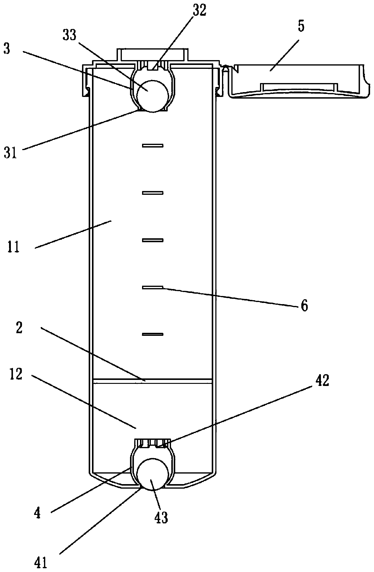
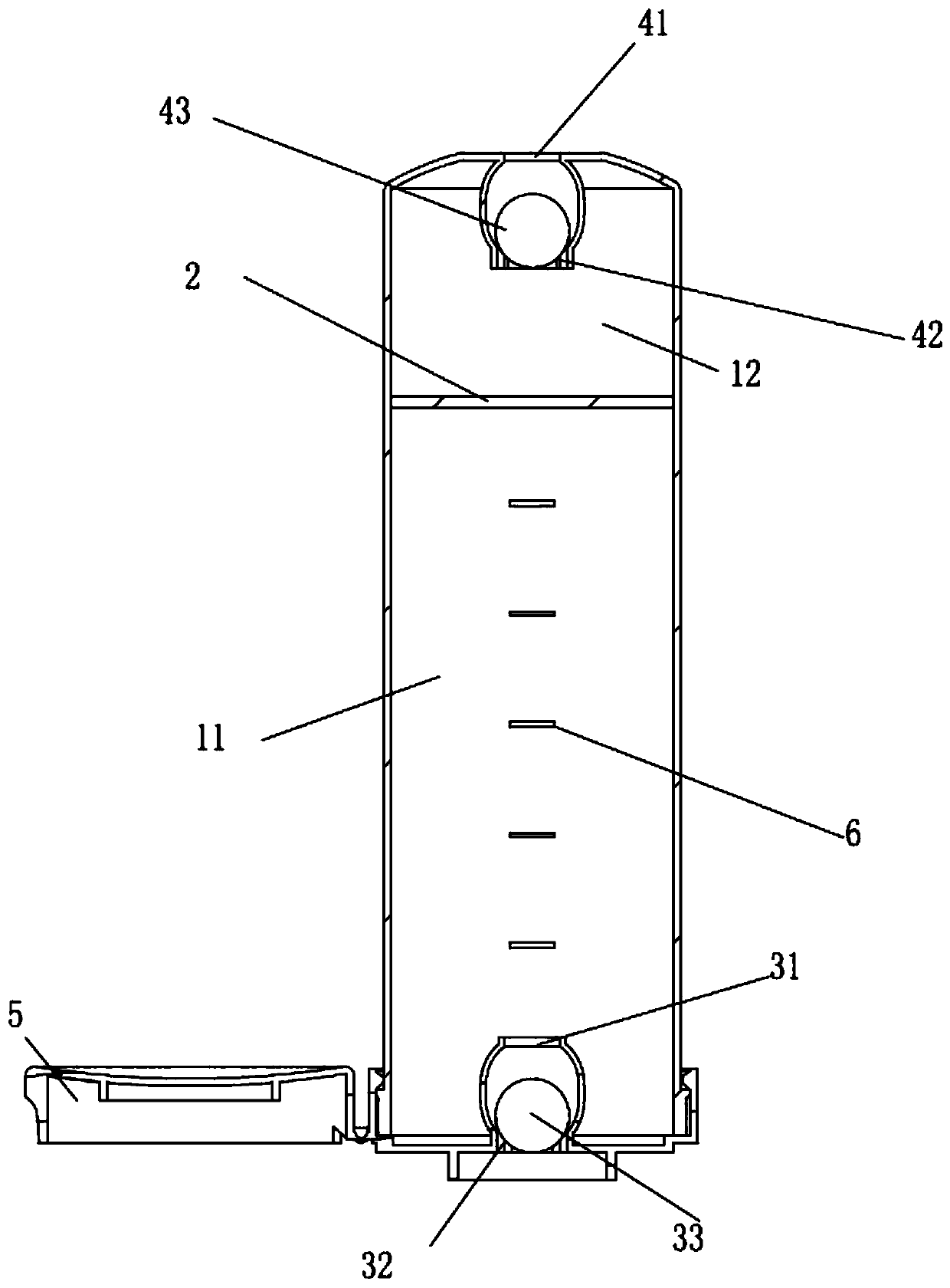
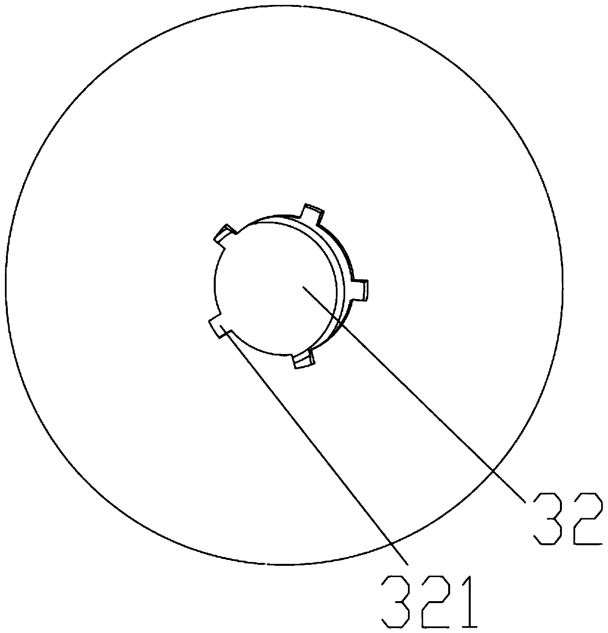
Piston type direct-pouring object-discharging container
A kind of container and piston type technology, which is applied in the field of piston type direct pouring container, can solve the problems of inconvenient use, hidden danger of sanitation, easy loss of container cover, etc., and achieve the effect of reasonable structural design and hygienic use
- Summary
- Abstract
- Description
- Claims
- Application Information
AI Technical Summary
Problems solved by technology
Method used
Image

Examples
Embodiment Construction
[0025] In the description of the present invention, it should also be noted that, unless otherwise clearly specified and limited, the terms "installation", "installation", "connection" and "connection" should be understood in a broad sense, for example, it may be a fixed connection, It can also be a detachable connection or an integral connection; it can be a mechanical connection or an electrical connection; it can be a direct connection or an indirect connection through an intermediary, and it can be the internal communication of two components. Those of ordinary skill in the art can understand the specific meanings of the above terms in the present invention in specific situations.
[0026] The following will clearly and completely describe the technical solutions in the embodiments of the present invention with reference to the accompanying drawings in the embodiments of the present invention. Obviously, the described embodiments are only some, not all, embodiments of the p...
PUM
 Abstract
Description
Claims
Application Information