Bridge guardrail template removing device

A technology for removal and formwork, which is applied in the direction of bridges, bridge parts, bridge construction, etc., can solve the problems of high risk of demolition and installation operations, low efficiency of formwork removal and installation, and improve the efficiency of formwork removal and stability and reliability, the effect of reducing investment

Pending Publication Date: 2019-09-27
HENAN HIGHWAY ENG GROUP +1
View PDF0 Cites 0 Cited by
  • Summary
  • Abstract
  • Description
  • Claims
  • Application Information

AI Technical Summary

Problems solved by technology

[0003] The purpose of the present invention is to make up for the problems of low construction efficiency and high

Method used


Image

  • Bridge guardrail template removing device
  • Bridge guardrail template removing device
  • Bridge guardrail template removing device

Examples


Example Embodiment

[0028] The present invention will be further explained below in conjunction with the drawings and specific embodiments:

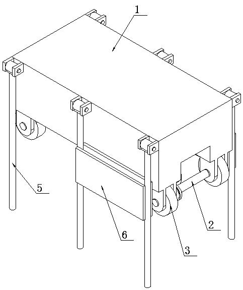
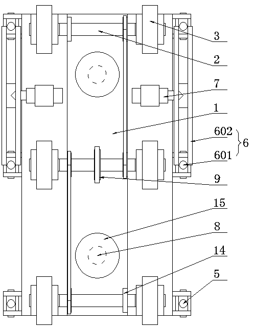
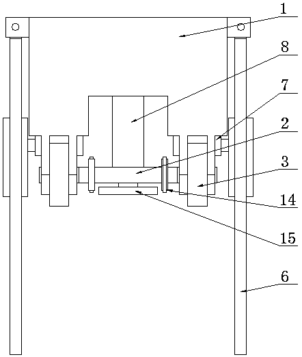
[0029] Such as Figure 1~Figure 7 As shown, a bridge guardrail template removal device includes a frame body 1, a walking component, a template fixing component, and a jacking component, and the walking component and the jacking and jacking component are located at the lower part of the frame 1. The template fixing components are located on both sides of the frame body 1;

[0030] The frame body 1 is a hollow shell;

[0031] The walking assembly is composed of a walking shaft 2, a walking wheel 3 and a walking motor 4. The walking shaft 2 is located under the frame 1 and is rotatably connected with the frame 1. The walking shafts 2 are arranged in a uniform array along the length of the frame 1. There are multiple, the traveling wheels 3 are fixedly arranged at both ends of the traveling shaft 2, the traveling motor 4 is fixedly installed inside the frame 1, and...


PUM


Abstract

The invention relates to a bridge guardrail template removing device. The bridge guardrail template removing device comprises a frame body, a traveling assembly, template fixing assemblies and a jacking assembly, wherein the traveling assembly and the jacking assembly are positioned at the lower part of the frame body, and the template fixing assemblies are positioned at two sides of the frame body. The bridge guardrail template removing device aims to solve the problems of low dismounting and mounting construction efficiency and high risk of dismounting and mounting operation of an existing template.

Description

Technical field [0001] The invention relates to the technical field of construction tools for bridges, in particular to a bridge guardrail template removing device. Background technique [0002] In the construction of modern bridge guardrail construction, the usual construction method is: firstly, the formwork is assembled one by one; after the assembly is completed, the linear elevation is adjusted and fixed; after the concrete pouring is completed, the strength is met, and the formwork is removed one by one; The processes of adjusting the height of the formwork-pouring concrete-removing the formwork-transferring the formwork are carried out in cycles. It consumes a lot of time, labor and machinery in construction, and the construction cost is high. At the same time, the self-weight of the formwork is large, and it is easy to lose stability when the formwork is dismantled in a whole piece using the existing method, the safety hazard is large, the construction efficiency is low,...

Claims


Application Information

Patent Timeline
IPC IPC(8): E01D21/00E01D19/10
CPCE01D19/103E01D21/00
Inventor 李志杰候青峰巫涛刘功刘伟袁高明何海刘艳雄金攀李海燕原瀚伦王鑫
Owner HENAN HIGHWAY ENG GROUP
Why Eureka
Try Eureka