Injection molding

Inactive Publication Date: 2012-10-11
RPC CONTAINERS
View PDF8 Cites 0 Cited by
  • Summary
  • Abstract
  • Description
  • Claims
  • Application Information

AI Technical Summary

Benefits of technology

[0015]As the molten plastic is injected into the mold while it is closing, the overall cycle time can be reduced (as mold closing can take place at the same time as injection). Even a very small decrease in cycle time can lead to a significant improvement in output over the entire life of the process.
[0016]Further, injecting molten plastic into an open mold is easier than injecting into a closed mold. Thus, the viscosity of the molte

Problems solved by technology

The standard process has certain disadvantages when used to form certain types of articles.
In turn, this high injection pressure will tend to force the mold halves apart, and so the clamping force needed to hold the mold halves together during injection must be increased.
This increases the power requirements and thus the overall costs of

Method used


Image

  • Injection molding
  • Injection molding

Examples


Example

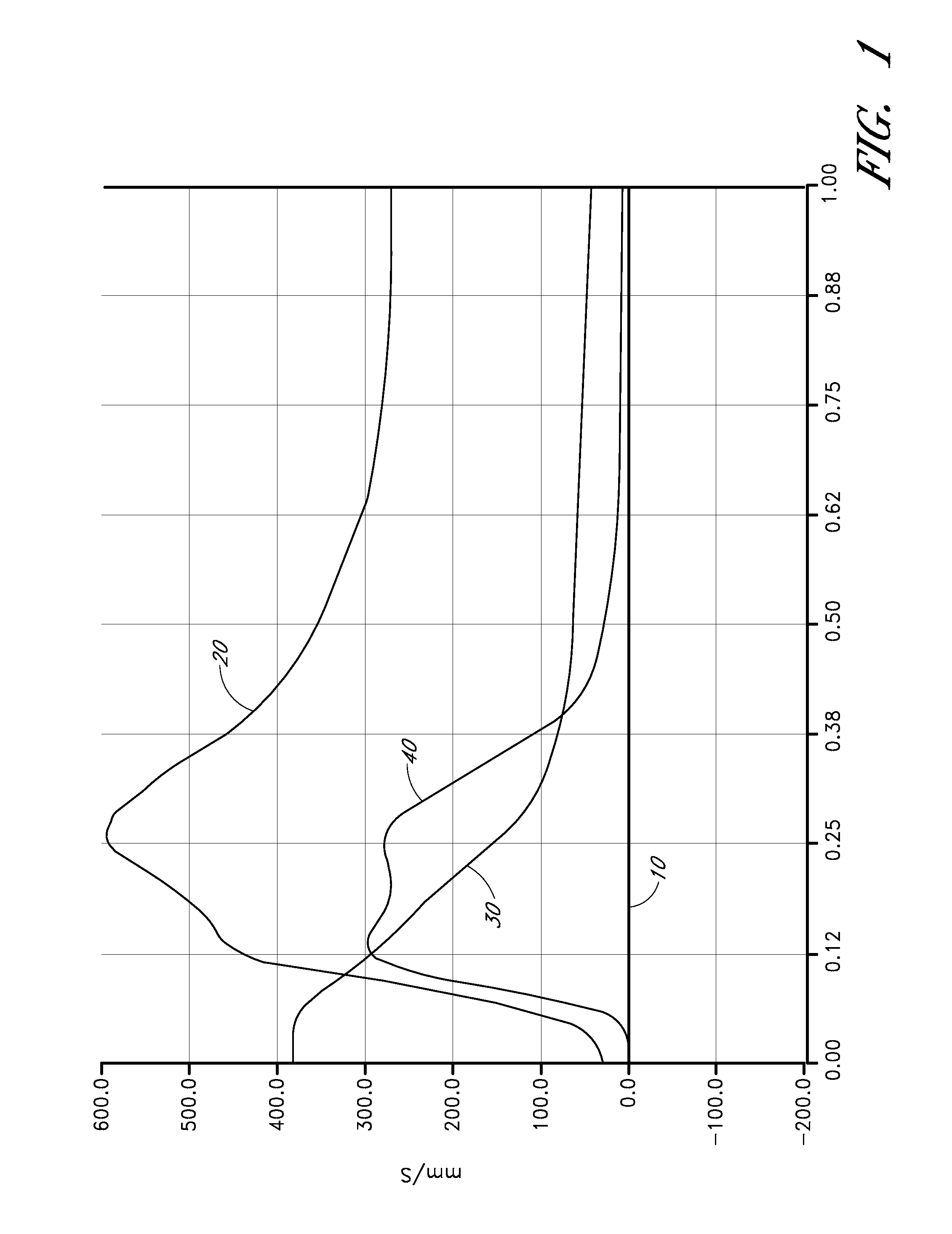
[0021]FIG. 1 is a graph showing the variation in time (measured along the x-axis in seconds) of four parameters during a conventional injection molding process. Specifically, the graph shows variation in mold part separation (line 10), injection pressure (line 20), injection screw displacement (line 30), and injection screw speed (line 40).

[0022]As this is a conventional injection molding process, in which molten plastic material is injected into a closed mold, the mold part separation (line 10) is 0 at all times during the process.

[0023]As the process starts, injection pressure (line 20) starts to increase. This leads to motion of the injection screw, shown by a decreasing injection screw displacement in line 30 and an increasing screw speed in line 40 at around 0.05 seconds. As the mold cavity fills with injected molten plastics material, the pressure rises, and the screw continues to move forward and accelerates in order to overcome this pressure.

[0024]When the mold cavity is nea...


PUM

PropertyMeasurementUnit
Timeaaaaaaaaaa
Timeaaaaaaaaaa

Abstract

In an injection molding process, the mold parts can be moved relative to each other (separation of the mold parts shown as line 50). Injection starts as the mold parts are being moved towards each other (injection pressure shown as line 60). The movement of the mold parts stops briefly as injection is completed, and the mold parts are then fully closed.

Description

BACKGROUND OF THE INVENTION[0001]1. Field of the Invention[0002]The present invention relates to a method of injection molding of plastic, and in particular to a method in which molten plastic is injected into a mold as the mold is closing.[0003]2. Description of the Related Art[0004]Injection molding is a very well-known method of forming articles from plastics. In a standard injection molding process, molten plastic is injected into a mold cavity formed between two mold halves, where it cools and hardens into the shape of the cavity.[0005]The standard process has certain disadvantages when used to form certain types of articles. For example, if the article to be formed has long thin parts, the injection pressure must be sufficient to force the molten plastic into the long thin parts of the mold cavity before the molten material solidifies. In turn, this high injection pressure will tend to force the mold halves apart, and so the clamping force needed to hold the mold halves togeth...

Claims


Application Information

Patent Timeline
IPC IPC(8): B29C45/56
CPCB29C45/561B29C45/7653B29C45/64B29C2045/562B29C45/18B29C45/80B29C45/00B29C45/0046B29C45/56
Inventor MALIK, KHALID M.
Owner RPC CONTAINERS
Why Eureka
Try Eureka