

Automatic tool changer
- Summary
- Abstract
- Description
- Claims
- Application Information
AI Technical Summary
Benefits of technology
Problems solved by technology
Method used
Image

Examples
first embodiment
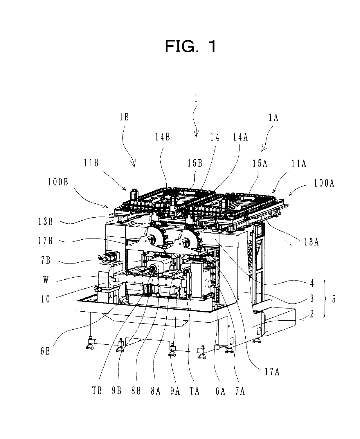
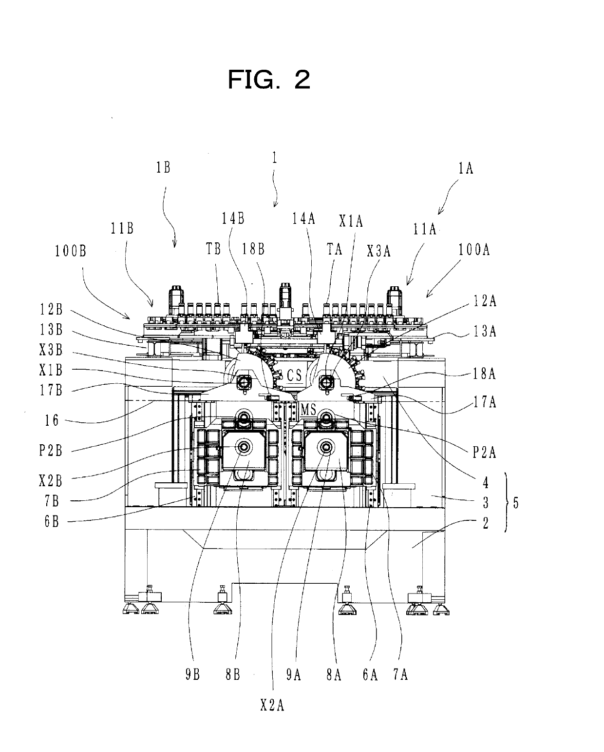
[0036]A machine tool 1 including automatic tool changers 100A, 100B according to the present invention will be described with reference to FIGS. 1 and 2. In the following, a machine tool 1 including two main spindles is cited as an example. FIG. 1 is a perspective view showing the entire machine tool 1, and FIG. 2 is a front view of the machine tool 1. The machine tool 1 includes a column bed 5 as a structural body. The column bed 5 includes a bed section 2, two column sections 3 vertically provided on both of left and right ends of the bed section 2, and a cross beam section 4 extending between upper portions of the two column sections 3. Two first saddles 6A, 6B are provided at a rear portion of the bed section 2 in a manner capable of moving in an X-axis direction (left-right direction in FIG. 2). Second saddles 7A, 7B are provided on front surfaces of the first saddles 6A, 6B, respectively, in a manner capable of moving in a Y-axis direction (top-bottom direction in FIG. 2). Mai...
fourth embodiment
[0074]Next, the present invention will be described with reference to FIG. 11. In each of the embodiments described above, an example is cited where the tool changer magazine 12A, 12B rotates clockwise from the origin position in FIG. 6 when performing tool replacement between the tool changer magazine 12A, 12B and the main spindle 9A, 9B. However, depending on a holding state of a tool in the tool holding section HA, HB of the tool changer magazine 12A, 12B, the cycle time may be more reduced by causing the tool changer magazine 12A, 12B to rotate counterclockwise than by causing the tool changer magazine 12A, 12B to rotate clockwise.
[0075]For example, in FIG. 11, after rotating clockwise from the origin position in (a) and reaching the position in (b) to perform tool replacement with respect to the main spindle (not shown), the tool changer magazine 12 stops at this position, and a tool after use that is attached to the main spindle is transferred to the tool changer magazine 12. ...
fifth embodiment
[0078]In each embodiment described above, an example is cited where the tool storage magazine 11A, 11B and the tool changer magazine 12A, 12B of the machine tool are disposed above the main spindle 9A, 9B, as shown in FIG. 2, but the present invention is also applicable to a machine tool having the tool storage magazine and the tool changer magazine disposed at a side of the main spindle. FIG. 14 is a schematic diagram showing a fifth embodiment for such a case.
[0079]In FIG. 14, the tool changer magazine 12A, 12B is disposed at a side of the respective main spindle 9A, 9B, and the tool changer magazine 12A, 12B performs transfer of a tool with respect to the tool storage magazine (not shown) which is also disposed at the side. The opening 16a for allowing tool replacement between the tool changer magazine 12A, 12B and the main spindle 9A, 9B is provided at the cover 16, on each of left and right, for partitioning the machining area MS and the non-machining area CS, in a manner corre...
PUM
 Abstract
Description
Claims
Application Information