Injection molding system

Active Publication Date: 2016-04-28
FANUC LTD
View PDF1 Cites 0 Cited by
  • Summary
  • Abstract
  • Description
  • Claims
  • Application Information

AI Technical Summary

Benefits of technology

[0024]The present invention, with the above configuration, can provide an injection molding system with reduced cycle time by performing a

Problems solved by technology

In addition to that, a large sized hand equipped with a movement mechanism of the

Method used


Image

  • Injection molding system
  • Injection molding system
  • Injection molding system

Examples


Example

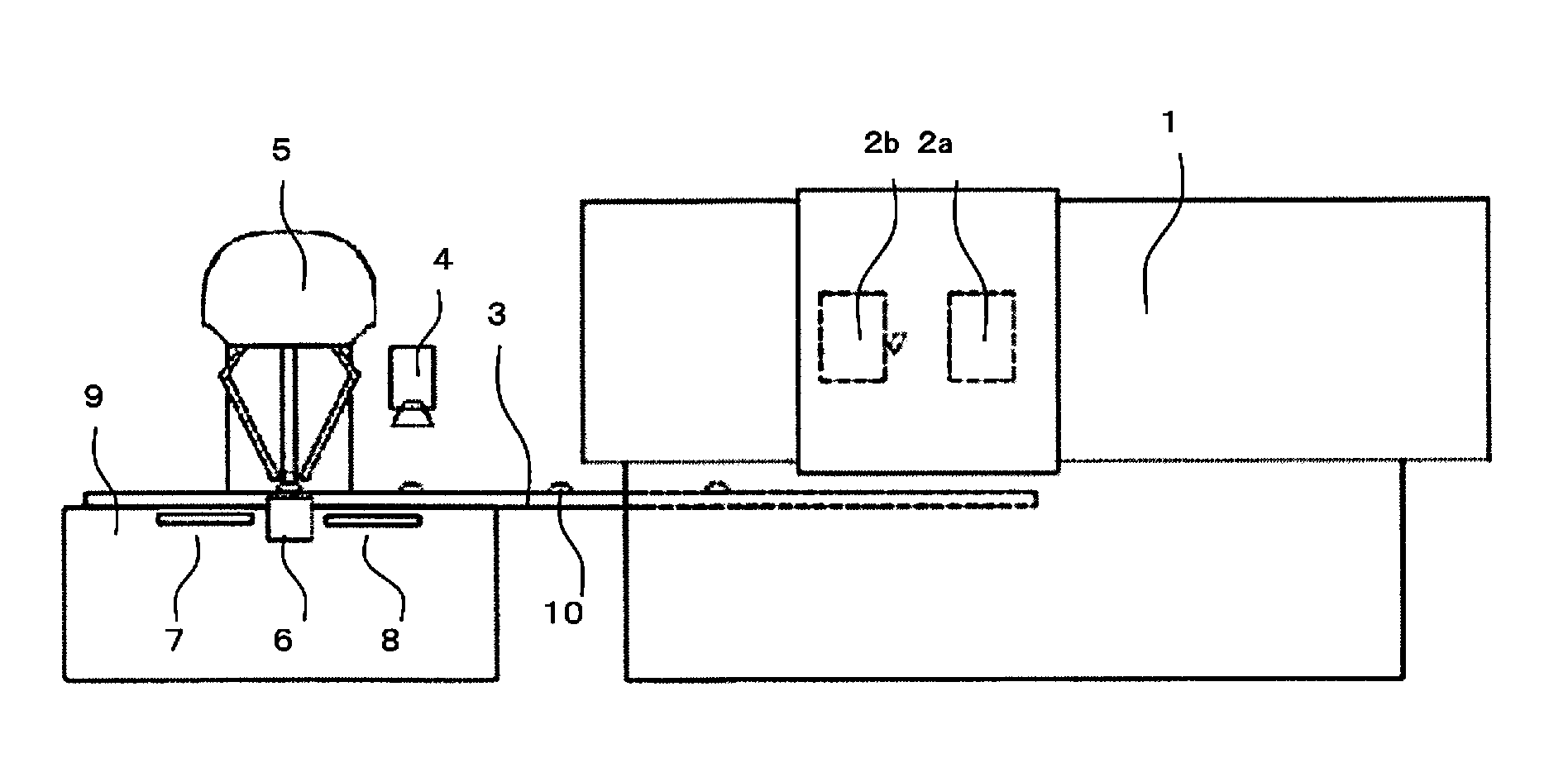
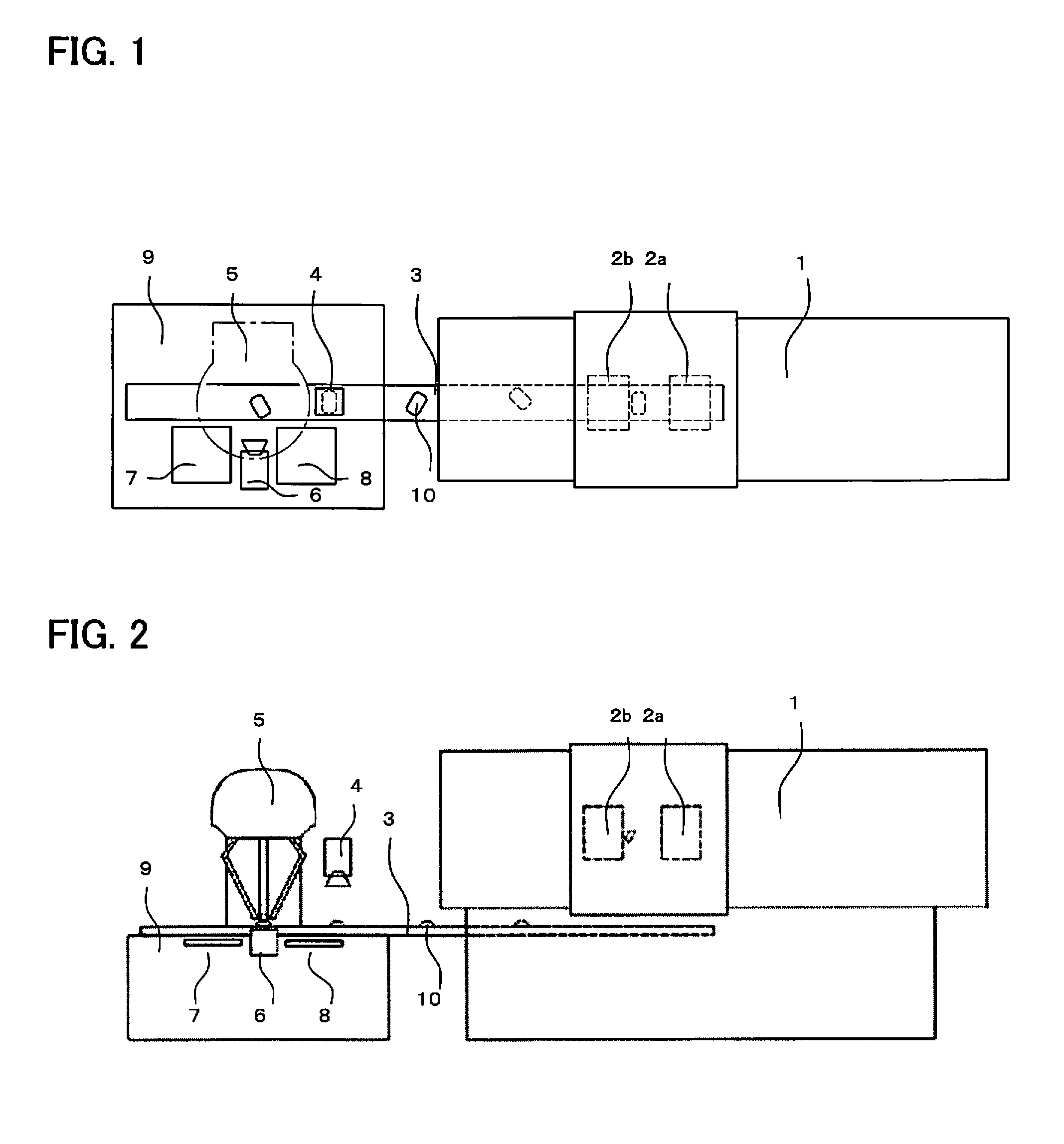
[0031]FIGS. 1, 2 are a schematic diagram of an injection molding system according to the present invention. The injection molding system consists of an injection molding machine 1, a mold 2, a conveyer 3, a position determination camera 4, a parallel link robot 5, an image processing inspection camera 6, a non defective item packing box 7, a defective item packing box 8, and a stand 9.

[0032]The parallel link robot 5 works as a molded item movement device, a molded item classification device, and an image analysis device. The image processing inspection camera 6 corresponds to the molded item photographing device in claim 1, and the second molded item photographing device in claim 4. The position determination camera 4 corresponds to the first molded item photographing device in claim 4.

[0033]A molded item 10 molded in the mold 2 of the injection molding machine 1 is demolded by ejection by an ejector not shown in the figure, to fall on the conveyer 3 installed below the mold 2, afte...


PUM

PropertyMeasurementUnit
Coloraaaaaaaaaa

Abstract

An injection molding system for making a molded item freely fall in demolding process from a mold, the injection molding system comprising:
a molded item photographing device, an image analysis device, and a molded item classification device, wherein the image analysis device is configured to perform analysis of appearance feature of the molded item, and make the item classification unit classify the molded item based on result of the analysis.

Description

RELATED APPLICATIONS[0001]The present application claims priority to Japanese Application Number 2014-216252, filed Oct. 23, 2014, the disclosure of which is hereby incorporated by reference herein in its entirety.BACKGROUND OF THE INVENTION[0002]1. Field of the Invention[0003]The present invention relates to an injection molding system configured to perform a set of work of inspecting, classifying, and packing the molded item fallen freely from a molding device continuously and in short time.[0004]2. Description of the Related Art[0005]The present invention relates to an injection molding system configured to perform a set of work of inspecting, classifying, and packing the molded item fallen freely from a molding device continuously and in short time.[0006]In molding by an injection molding machine, there is a case in which a molded item is made to fall to a box for reducing cycle time. The molded item in the box is sent to inspection process and inspected whether the item is defe...

Claims


Application Information

Patent Timeline
IPC IPC(8): B29C45/76
CPCB29C45/7686B07C5/3422B29C45/1769B29C45/7626B29C2945/76769B29C45/17
Inventor TSUCHIYA, NOBUATSU
Owner FANUC LTD
Why Eureka
Try Eureka